IES-P3073GC Series User Manual
ORing Industrial Networking Corp
11
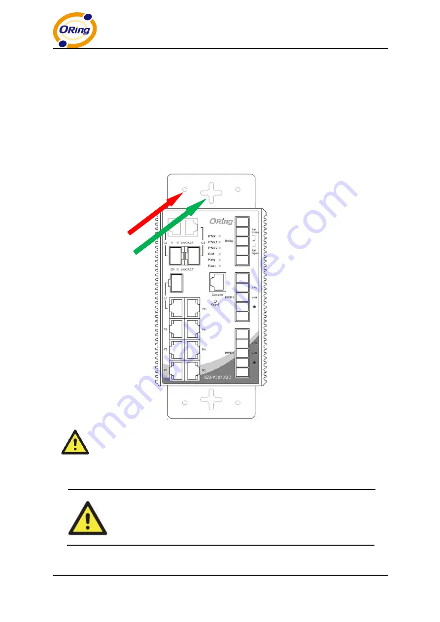
2. Use the switch, with wall mount plates attached, as a guide to mark the correct locations of
the four screws.
3. Insert screws through the round screw holes (the red arrow as below) on the sides or
through the cross-shaped aperture (the green arrow as below) in the middle of the plate and
fasten the screw to the wall with a screwdriver.
4. If the screw goes through the cross-shaped aperture, slide the switch down before
tightening the screw.
Note: Instead of screwing the screws in all the way, leave about 2 mm to allow room
for sliding the wall mount panel between the wall and the screws.
3.3 Wiring
WARNING
Do not disconnect modules or wires unless power has been switched off or
the area is known to be non-hazardous. The devices may only be connected
to the supply voltage shown on the type plate.


