IES-P3073GC Series User Manual
ORing Industrial Networking Corp
8
2.1.2 LED
LED
Color
Status
Description
PWR
Green
On
DC power on
PW1
Green
On
DC power module 1 activated
PW2
Green
On
DC power module 2 activated
R.M
Green
On
System running in Ring Master mode
Ring
Green
On
System running in Ring mode
Blinking
Ring structure is broken (i.e. part of the
ring is disconnected)
Fault
Amber
On
Faulty relay (power failure or port
malfunctioning)
10/100Base-T(X) Fast Ethernet ports
LNK/ACT
Green
On
Ethernet links connected
Blinking
Transmitting data
Speed
Amber
On
Port work on 100Mbps transmission
Off
Port work on 10/1000Mbps transmission
SFP Combo ports
LNK/ACT
Green
On
Ethernet links connected
Blinking
Transmitting data
2.2 Rear Panel
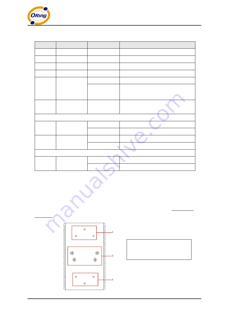
On the rear panel of the switch sit three sets of screw holes. The two sets placed in
triangular patterns on both ends of the rear panel are used for wall-mounting (red boxes in the
figure below) and the set of four holes in the middle are used for Din-rail installation (blue box
in the figure below). For more information on installation, please refer to 23.1 Din-rail
Installation.
1. Wall-mount screw holes
2. Din-rail screw holes


