
100
VCCX2 Controller Technical Guide
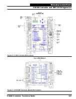
VCCX2 Controller LEDs
The VCCX2 Controller is equipped with LEDs that can be used
to verify operation and perform troubleshooting. There are LEDs
for communication, operation modes, and diagnostic codes. The
VCCX2 Controller has 26 LEDs—10 used for operation and
status, eight are used for relays, and eight are used for binary
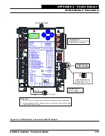
inputs. See
Figure 46, page 101
for the LED locations. The
LEDs associated with these inputs and outputs allow you to see
what is active without using a voltmeter. The LEDs and their
uses are as follows:
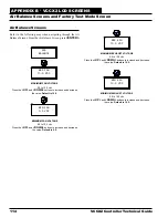
Operation LEDs - Factory Troubleshooting
POWER
- This green LED will light up to indicate that 24 VAC
power has been applied to the controller.
APP HB
- This green LED will light up and blink continuously
to indicate the application software is working properly.
OS HB
- This green LED will light up and blink continuously
to indicate the operating system is working properly.
WDOG
- This green LED will light up and stay lit to indicate
the operating system is working properly.
Diagnostic LEDs
ALARM
- This red LED is a diagnostic blink code LED. It will
light up and stay lit when there is an alarm present. The type of
alarm will display on the LCD display.
STATUS 1
- This red LED is a diagnostic blink code LED.
Under normal operation, it should not be blinking. If the LED
is blinking non-stop along with Status 2 LED, the controller is
resetting factory defaults.
STATUS 2
- This red LED is a diagnostic blink code LED. If the
software is running, this LED should blink at a rate of one blink
every 10 seconds. If there is an override, the LED will blink two
times every 10 seconds. And finally, if one of the outputs is in
Force Mode, the LED will blink three times every 10 seconds.
Communication LEDs
EBUS
- This yellow LED will blink to signal E-BUS
communications.
LOOP COMM
- This yellow LED will light up and blink
continuously to indicate the VCCX2 Controller is communicating.
BACnet
®
- This yellow LED will light up and blink continuously
to indicate BACnet
®
communications.
Relay LEDs
RLY1
- This green LED will light up when the Supply Fan is
enabled and will stay lit as long as the Supply Fan is active.
RLY2 - RLY8
- These green LEDs will light up when the relays
are enabled and will stay lit as long as they are active.
Binary Input LEDs
BIN1
- This green LED will light up when the Proof of Flow
Contact is closed.
BIN2
- This green LED will light up when the Dirty Filter
Switch is closed.
BIN3
- This green LED will light up when the Hood On/Off
Switch is closed.
BIN4
- This green LED will light up when the Remote Occupied
Switch is closed.
BIN5
- This green LED will light up when the Remote Cooling
Contact is closed.
BIN6
- This green LED will light up when the Remote Heating
Switch is closed.
BIN7
- This green LED will light up when the Remote
Dehumidification Switch is closed.
BIN8
- This green LED will light up when the Emergency
Shutdown Contact is closed.
VCC-X EM1 Expansion Module LEDs
The VCC-X EM1 Expansion Module is equipped with 4 LEDs
that can be used as very powerful troubleshooting tools. See
Figure 47, page 101
for LED locations. The LEDs and their
uses are as follows:
PWR
- This LED will light up to indicate that 24 VAC power
has been applied to the controller.
ALARM
- If the module does not receive communications for
more than 1 minute, this LED will light up, the relays will turn
off, and the Analog Outputs will go to 0 VDC.
STAT
- If the software is running, this LED should blink at a
rate of 1 blink per second.
COMM
- Every time the module receives a valid E-BUS request
from the VCCX2 Controller, this LED will blink on and then
off, signifying that it received a valid request and responded.
Binary Input LEDs
BIN1
- This green LED will light up when the Return/Exhaust
Proof of Flow contact is closed.
RSM LEDs
The RSM LEDs are described in the RSM Technical Guides.
TROUBLESHOOTING
VCCX2 Controller and EM1 LED Diagnostics


