122
VCCX2 Controller Technical Guide
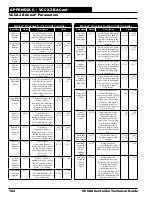
BACnet
®
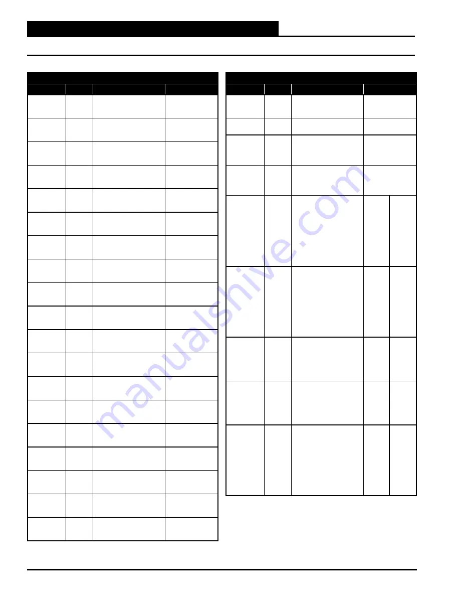
Properties for the VCCX2 Controller
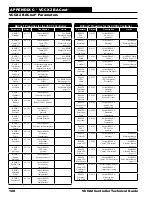
Parameter
Object
Description
Limits
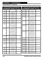
SUB 1
Pressure 2
AI: 257
Current Subcooling
Module 1 liquid line
pressure 2 reading
SUB 1
Pressure 3
AI: 258
Current Subcooling
Module 1 liquid line
pressure 3 reading
SUB 1
Saturation 1
AI: 259
Subcooling
Module 1 saturation
temperature 1 reading
SUB 1
Saturation 2
AI: 260
Subcooling
Module 1 saturation
temperature 2 reading
SUB 1
Saturation 3
AI: 261
Subcooling
Module 1 saturation
temperature 3 reading
SUB 1
Line Temp 1
AI: 262
Subcooling
Module 1 liquid line
temperature 1 reading
SUB 1
Line Temp 2
AI: 263
Subcooling
Module 1 liquid line
temperature 2 reading
SUB 1
Line Temp 3
AI: 264
Subcooling
Module 1 liquid line
temperature 3 reading
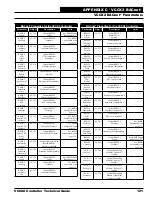
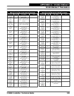
SUB 2
Sub Cool 1
AI: 265
Current Subcooling
Module 2 Sub Cool 1
reading
SUB 2
Sub Cool 2
AI: 266
Current Subcooling
Module 2 Sub Cool 2
reading
SUB 2
Sub Cool 3
AI: 267
Current Subcooling
Module 2 Sub Cool 3
reading
SUB 2
Pressure 1
AI: 268
Current Subcooling
Module 2 liquid line
pressure 1 reading
SUB 2
Pressure 2
AI: 269
Subcooling
Module 2 liquid line
pressure 2 reading
SUB 2
Pressure 3
AI: 270
Subcooling
Module 2 liquid line
pressure 3 reading
SUB 2
Saturation 1
AI: 271
Subcooling
Module 2 saturation
temperature 1 reading
SUB 2
Saturation 2
AI: 272
Subcooling
Module 2 saturation
temperature 2 reading
SUB 2
Saturation 3
AI: 273
Subcooling
Module 2 saturation
temperature 3 reading
SUB 2
Line Temp 1
AI: 274
Subcooling
Module 2 liquid line
temperature 1 reading
SUB 2
Line Temp 2
AI: 275
Subcooling
Module 2 liquid line
temperature 2 reading
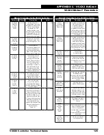
APPENDIX C - VCCX2 BACnet
®
VCCX2 BACnet
®
Parameters
BACnet
®
Properties for the VCCX2 Controller
Parameter
Object
Description
Limits
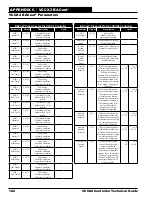
SUB 2
Line Temp 3
AI: 276
Subcooling
Module 2 liquid line
temperature 2 reading
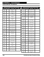
Enter Water
Pump
AI: 277
Current status of Entering
Water Temperature
Return
Plenum
Pressure
Status
AI: 278
Current value of the Return
Plenum Pressure Sensor
Return
Plenum
Control
Signal
AI: 279
Current Return Plenum
Control Signal. (Motorized
Exhaust Damper)
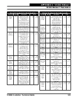
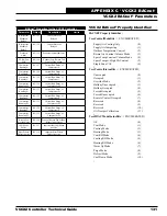
Occupied
Cooling
Setpoint
AV: 1
If the control temperature
rises one deadband above
this setpoint, the control will
activate the cooling
demand. This setpoint does
not determine the mode in
Occupied operation if the
unit is configured for Supply
Air Cooling or Supply Air
Tempering.
1°F
-17.2°C
110°F
43.3°C
Occupied
Heating
Setpoint
AV: 2
If the control temperature
drops one deadband below
this setpoint, the control
will activate the heating
demand. This setpoint does
not determine the mode in
Occupied operation if the
unit is configured for
Supply Air Cooling or
Supply Air Tempering.
1°F
-17.2°C
110°F
43.3°C
Hood On
Cooling
Setpoint
AV: 3
This is the Cooling Mode
Enable Setpoint used only
in Hood On Mode or Space
Temperature Control of High
Percentage Outdoor Air
Units or VAV Tempering.
1°F
-17.2°C
110°F
43.3°C
Hood On
Heating
Setpoint
AV: 4
This is the Heating Mode
Enable Setpoint used only
in Hood On Mode or Space
Temperature Control of High
Percentage Outdoor Air
Units or VAV Tempering.
1°F
-17.2°C
110°F
43.3°C
Unoccupied
Cooling
Offset
AV: 5
During the Unoccupied
Mode of Operation, this
Setpoint offsets the
Occupied Cooling Setpoint
up by this user-adjustable
amount. If you do not want
Cooling to operate during
the Unoccupied Mode, use
the default setting of 30°F
for this setpoint.
0°F
0°C
30°F
16.6°C

