125
VCCX2 Controller Technical Guide
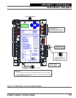
APPENDIX C - VCCX2 BACnet
®
VCCX2 BACnet
®
Parameters
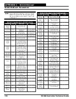
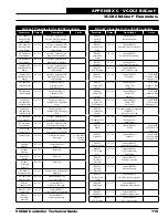
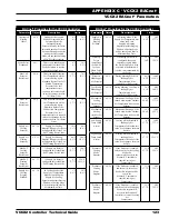
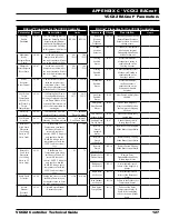
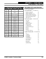
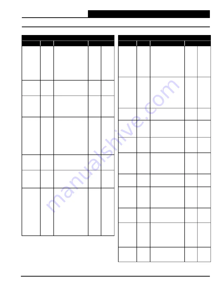
BACnet
®
Properties for the VCCX2 Controller
Parameter
Object
Description
Limits
Minimum
Main Fan
VFD in
Heating
Mode
AV: 46
In Single Zone VAV
configuration, this is the
fan speed at which the VFD
will start when Heating
is initiated. In a VAV
configuration this is the
lowest fan speed allowed in
the Heating Mode. In CAV
and MUA configurations
this should be set to 100%.
0
100
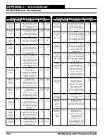
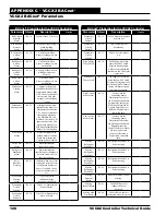
Minimum
Main Fan
VFD in Vent
Mode
AV: 47
Speed at which the VFD
will operate in the Vent
Mode in Single Zone VAV.
0
100
Maximum
Economizer
in Heating
Mode
AV: 48
Max position the
Economizer Damper can
open to in Supply Air
Tempering during Heating
Mode. Takes priority over
Max Position in High CO
2
.
0
100
Minimum
Economizer
Position
AV: 49
The minimum position
of the Outdoor Air
damper in the Occupied
Mode. This can be reset
upwards based on indoor
CO
2
levels. NOTE: See
Economizer Override via
BACnet
®
section in the
Economizer area of the
Sequence of Operations for
additional information.
0
100
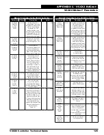
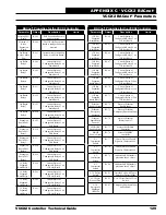
Maximum
Economizer
CO
2
Reset
Limit
AV: 50
The maximum value the
Economizer Minimum
Position can be reset up to
during CO
2
override.
0
100
Minimum
Carbon
Dioxide
Setpoint
AV: 51
This is the threshold
CO
2
level at which the
Economizer Min Damper
Position Setpoint will begin
to be reset higher.
0
2000
Maximum
Carbon
Dioxide
Setpoint
AV: 52
This is the CO
2
level at
which the Economizer Min
Damper Position will be
reset to the Economizer Max
Position in High CO
2
. In
between the Min and Max
CO
2
levels the Economizer
Min Damper Position will
be proportionally reset
between the configured Min
Damper Position and the
Max Position in
High CO
2
.
0
2000
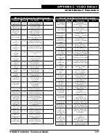
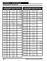
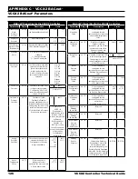
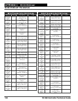
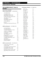
BACnet
®
Properties for the VCCX2 Controller
Parameter
Object
Description
Limits
Indoor
Humidity
Setpoint Low
Reset Limit
AV: 53
On indoor controlled (non
MUA) units, this is the
Humidity setpoint at
which the unit leaves
Dehumidification. During
Coil Temp Reset, this is the
lowest Space RH value that
corresponds to the High Coil
Temp Setpoint.
0
100
Indoor
Humidity
Setpoint High
Reset Limit
AV: 54
On indoor controlled (non
MUA) units, this is the
Humidity setpoint at
which the unit initiates
Dehumidification. During
Coil Temp Reset, this is the
highest Space RH value that
corresponds to the Low Coil
Temp Setpoint.
0
100
Duct Static
Pressure
Setpoint
AV: 55
Current Static
Pressure Setpoint.
.10
3.0
Duct Static
Pressure
Control
Deadband
AV: 56
Value above and below
the Duct Static Pressure
Setpoint where no control
change occurs.
.01
.5
Building
Pressure
Control
Setpoint
AV: 57
Building Pressure
Setpoint or Exhaust Duct
Static Pressure Setpoint.
-.20
3.0
Building
Pressure
Control
Deadband
AV: 58
Value above and below the
Building Pressure
Setpoint or the Exhaust Duct
Static Pressure Setpoint
where no control change
occurs.
.01
.5
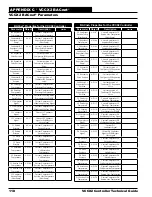
Minimum
Outdoor CFM
Requirement
AV: 59
Minimum Outdoor
Airflow CFM Setpoint
.10K
200K
Outdoor
CFM Control
Deadband
AV: 60
Controls rate of change
for damper signal. As OA
CFM moves further from
setpoint within this window,
the damper makes a larger
change.
10
1000
Single
Zone VAV
Fan Speed
Integral
AV: 61
The Integral Constant for
Single Zone VAV Fan
Control.
0
10
Relay
Run-time
Hours
Warning
Limit
AV: 62
If any configured relay’s run
time exceeds this number
of hours of operation, a
warning alarm is generated
so that
periodic maintenance can be
performed.
0
30000
Cooling
Mode Head
Pressure
Setpoint
AV: 63
Head Pressure Setpoint in
the Cooling Mode.
250
450


