


24
VCCX2 Controller Technical Guide
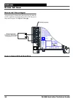
General
Correct wiring of the VCCX2 Controller is the most important
factor in the overall success of the controller installation process.
In general, most VCCX2 Controllers are factory installed and
wired at the AAON
®
factory. It is also possible to purchase
these controllers through your local AAON
®
representative
for installation in the field. Some of the following information
pertains to field wiring and may not apply to your installation if
it was pre-wired at the factory. However, if troubleshooting of
the controller is required, it is a good idea to be familiar with the
system wiring, no matter if it was factory or field wired.
Controller Mounting
When the controller is to be field mounted, it is important to
mount the controller in a location that is free from extreme high
or low temperatures, moisture, dust, and dirt. See
Table 1, this
page
for a list of the required operating conditions for the VCCX2
Controller and associated expansion modules.
The VCCX2 Controller is housed in a plastic enclosure. It is
designed to be mounted by using the three mounting holes in
the enclosure base. The VCCX2 Controller needs to be installed
in an environment which can maintain a temperature range
between -22°F and 158°F not to exceed 95% RH levels (non-
condensing). Be careful not to damage the electronic components
when mounting the controller.
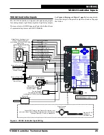
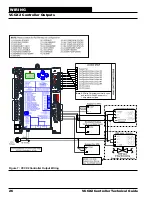
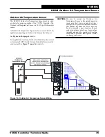
Wiring
The VCCX2 Controller and expansion modules must be
connected to a 24 VAC power source of the proper size for the
calculated VA load requirements. All transformer sizing should
be based on the VA rating listed in
Table 1, this page.
Please carefully read and apply the following information when
wiring the VCCX2 Controller, RSMs, and Expansion Modules.
1. All wiring is to be in accordance with local and
national electrical codes and specifications.
2. All 24 VAC wiring must be connected so that all
ground wires remain common. Failure to follow this
procedure can result in damage to the controller and
connected devices.
3. Minimum wire size for 24 VAC wiring should be
18-gauge.
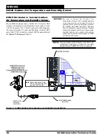
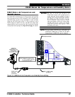
4. Minimum wire size for all sensors should be 24-gauge.
Some sensors require two-conductor wire and some
require three-or four-conductor wire.
5. Minimum wire size for 24 VAC thermostat wiring
should be 22-gauge.
6. Be sure that all wiring connections are properly
inserted and tightened into the terminal blocks. Do
not allow wire strands to stick out and touch adjoining
terminals which could potentially cause a short circuit.
7. When communication wiring is to be used to
interconnect VCCX2 Controllers together or to
connect to other communication devices, all wiring
must be plenum-rated, minimum 18-gauge, two-
conductor, twisted pair with shield. AAON can supply
communication wire that meets this specification and
is color coded for the network or local loop. Please
consult your AAON distributor for information. If
desired, Belden #82760 or equivalent wire may also
be used.
8. Before applying power to the VCCX2 Controller,
be sure to recheck all wiring connections and
terminations thoroughly.
Powering Up
When the VCCX2 and connected modules are first powered
up, the POWER LED should light up and stay on continuously.
If it does not light up, check to be sure that you have 24 VAC
connected to the controller, that the wiring connections are tight,
and that they are wired for the correct polarity. The 24 VAC power
must be connected so that all ground wires remain common. If
after making all these checks, the POWER LED does not light
up, please contact AAON Controls Support for assistance.
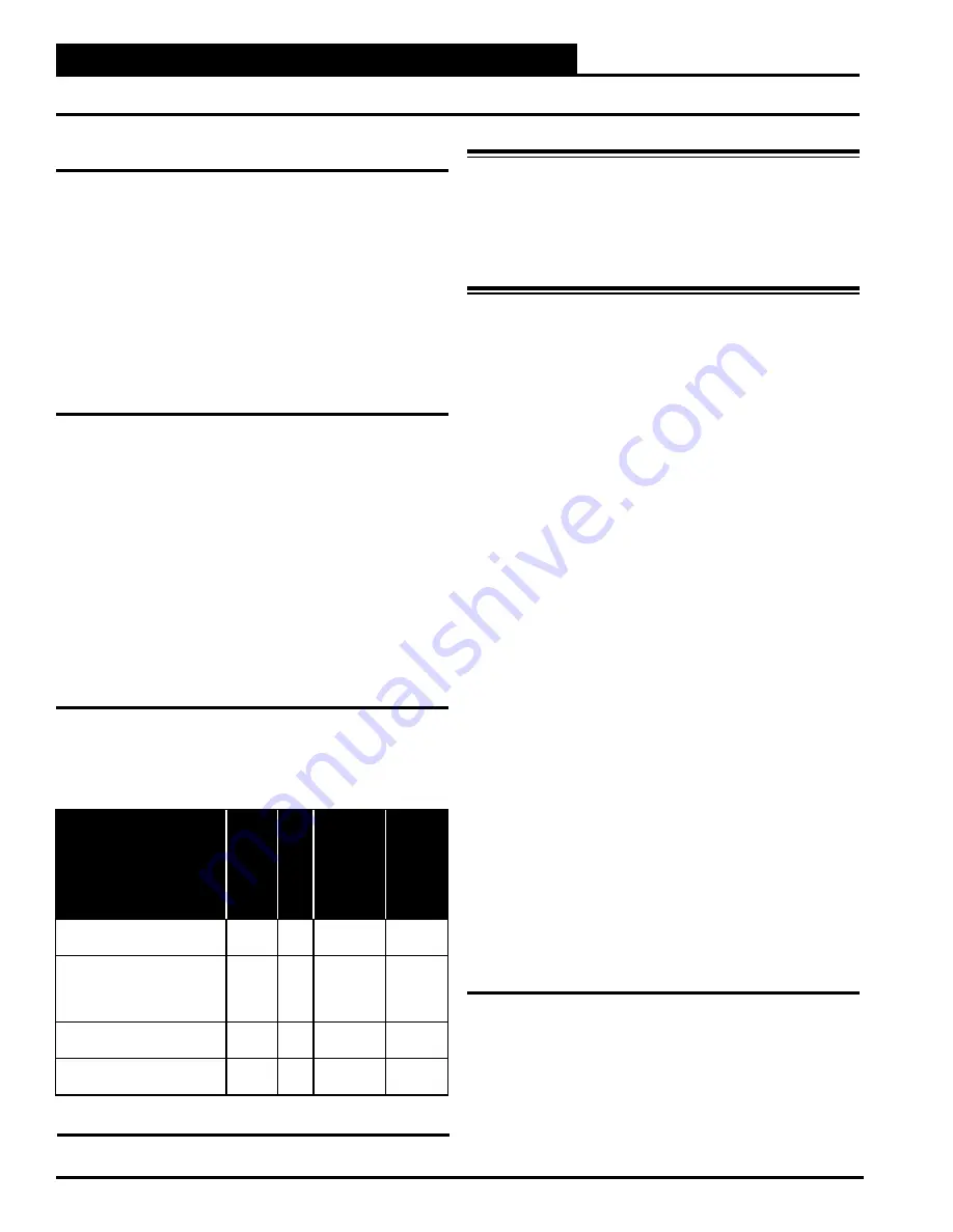
Control
Device
Voltage
VA
Load
Temperature
Humidity
(Non-
Condensing)
VCCX2 Controller
18-30
VAC
15
-22°F to
158°F
0-95%
RH
RSMD, RSMV, RSMV-HP,
RSMZ Refrigerant System
Modules and Subcool
Monitor
18-30
VAC
18
-22°F to
158°F
0-95%
RH
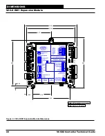
VCCX EM1
Expansion Module
18-30
VAC
5
-22°F to
158°F
0-95%
RH
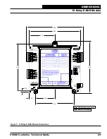
12 Relay E-BUS
Expansion Module
18-30
VAC
15
-22°F to
158°F
0-95%
RH
Table 1: Voltage and Environment Requirements
WARNING:
When using a single transformer to
power multiple controllers or expansion
modules, the correct polarity must always
be maintained between the boards. Failure
to observe correct polarity will result in
damage to the controller and expansion
modules.
WIRING
Important Wiring Considerations


