


45
VCCX2 Controller Technical Guide
WARNING:
Observe Polarity! All boards must be
wired with GND-to-GND and 24 VAC-
to-24 VAC. Failure to observe polarity
will result in damage to one or more of the
boards. Expansion modules must be wired
in such a way that the expansion modules
and the controller are always powered
together. Loss of power to the expansion
module will cause the controller to become
inoperative until power is restored to the
expansion module.
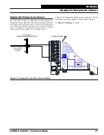
Caution:
It is strongly recommended that you use
pneumatic tubing instead of relocating
the sensor. Extending the wires could
cause voltage drop problems.
ASM01640
Exhaust Static
Pressure Sensor
Set jumper to 0-10 V
(by others)
Belimo Actuator wiring shown.
Consult factory for other
manufacturer wiring instructions.
Economizer Damper Actuator
(Belimo Actuator shown)
Connect to
Expansion Module(s)
(when used)
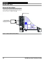
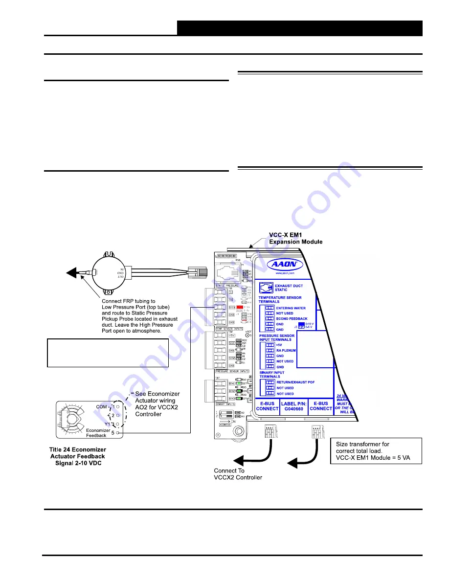
Exhaust Duct Static Pressure Sensor
The ASM01640 Static Pressure Sensor plugs directly into the
EM1’s Static Pressure port. The Duct Static Pressure Sensor
reading is used to determine current Exhaust Duct Static Pressure.
This Static Pressure reading is used to control the output signal
(AO4 on the VCCX2 Controller) supplied to the Exhaust Fan
VFD. See
Figure 26, this page
for wiring.
Title 24 Economizer Actuator
Feedback
If the controller has been configured for Title 24 Economizer
operation, the Economizer Actuator Feedback signal will be
wired to the VCC-X EM1’s SIG3 input. The jumper should be
set to 0-10 V. See
Figure 26, this page
for wiring.
Figure 26: VCC-X EM1 Exhaust Duct Static Pressure and Economizer Actuator Feedback Wiring
WIRING
VCC-X EM1 Expansion Module Inputs


