48
VCCX2 Controller Technical Guide
Return Air Bypass
The VCCX2 Controller can be configured for AAON
®
Return Air
Bypass applications. These provide improved moisture removal
capabilities while utilizing internal space loads for reheat by
redirecting Return Air around the Evaporator Coil instead of
through the coil. See the AAON
®
Return Air Bypass application
section of this manual on
page 10
for complete operation details.
The AAON
®
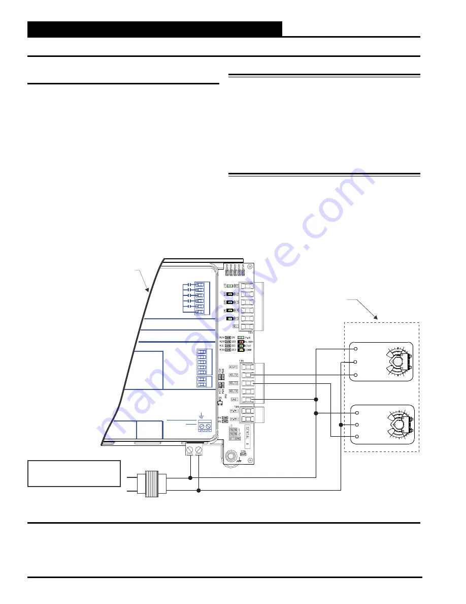
Return Air Bypass applications utilize a Return
Air Bypass Damper Actuator and a Return Air Damper Actuator
to modulate the Return Air and Return Air Bypass Dampers to
control the amount of air that is redirected around the Evaporator
Coil.
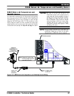
The output is configured for 2-10 VDC direct acting operation.
See
Figure 29, this page
for detailed wiring of the Return Air
Bypass and Return Air Damper Actuators.
WARNING:
Observe Polarity! All boards must be
wired with GND-to-GND and 24 VAC-
to-24 VAC. Failure to observe polarity
will result in damage to one or more of the
boards. Expansion modules must be wired
in such a way that the expansion modules
and the controller are always powered
together. Loss of power to the expansion
module will cause the controller to become
inoperative until power is restored to the
expansion module.
Figure 29: Return Air Bypass Wiring
+
2
4
V
A
C
G
N
D
R
E
L
A
Y
C
O
N
T
A
C
T
R
A
T
IN
G
IS
1
A
M
P
M
A
X
@
2
4
V
A
C
R1
R2
R3
R4
R5
RELAY OUTPUT
TERMINALS
ANALOG OUTPUT TERMINALS
GN D
N OT U SED
N OT U SED
R ETU R N D A MPER
R ETU R N B YPA SS
C H ILLED WATER
EXH. DAMPER
E-BUS
CONNECT
24 VAC PO WER
O NLY
WARNING !
PO LARITY
POWER INPUT
TERMINAL BLOCK
VCC-X E
EXPANSION
M1
AAON P/N: ASM01691
LABEL P/N:
G040660
RC
VCC-X EM1
Expansion Module
18-30 VAC
GND
Line Voltage
Size transformer for
correct total load.
VCC-X E 1 Module = 5 VA
M
2 +
Y1
3
COM
1
2 +
Y1
3
COM
1
Belimo Actuator wiring
shown. Consult factory
for other manufacturer
wiring instructions.
Damper Actuator
Return Air
Return Air Bypass
Damper Actuator
WIRING
Return Air Bypass

