


62
VCCX2 Controller Technical Guide
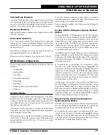
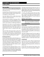
MODGAS-XWR2 Wiring
The ASM01695 MODGAS-XWR2 is designed to be used with
White-Rodgers
®
valves only. It will modulate up to two White-
Rodgers
®
gas valves to maintain a desired Discharge (Supply)
Air Temperature (up to four modulating gas valves may be
controlled when a second MODGAS-XWR2 is configured as a
slave module). The module also controls the speed of the induced
draft fan to maintain proper combustion in the heat exchanger.
The module can be used as a stand-alone unit or be connected
to the 12 Relay E-BUS Expansion Module (stand-alone only)
or VCCX2 Controller using an E-BUS cable. See
Figure 43,
this page
.
The following information will be passed between the MODGAS-
XWR2 and the VCCX2 Controller:
•
Heat activation command
•
Heating Discharge Setpoint
•
The offset for the Supply Air Temperature Sensor
•
High Limit Temperature Setpoint
•
If the communication is interrupted between the
MODGAS-XWR2 and the VCCX2 Controller, the
MODGAS-XWR2 will revert to stand-alone operation.
For more information, refer to the
MODGAS-XWR2 Technical
Guide
.
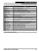
Proof of Ignition
Signal 1 (24 VAC)
Fan Enable
Low Speed Fan
Heat Valve 1
Heat Valve 2
Fixed Heat Stage 3
Fixed Heat Stage 4
Proof of Ignition
Signal 2 (24 VAC)
Note:
1. 24 VAC must be connected so
that all ground wires remain common.
2. All wiring to be in accordance with
local and national electrical codes
and specifications.
Connect Supply Air Temperature sensor
to AI3 and GND to VCCX2.
Mount in supply
air duct
Supply Air
Temperature
Sensor
The SAT OPTIONS jumper setting should
be set to 1. Only one Supply Air Temperature
sensor can be used per application.
Line
Voltage
40 VA
Transformer
minimum
GND
18-30
VAC
Check your fan
relay wiring (RLY 1)
schematic for proper
wiring.
EBC E-BUS cable connects to VCCX2
expansion port
Modulating
Gas Valve 2
(Modulates with
Valve 1 as 1 stage)
Modulating
Gas Valve 1
(Modulates with
Valve 2 as 1 stage)
GND
AUX BIN
HEAT EN
RESET IN
OPTIONS
GND
SAT
GND
AUX AIN
STATUS
ALARM
COMM
POWER
YS102408 REV 3
RLY1
RLY2
RLY3
RLY4
RLY5
RLY6
COMMON
PO-IGN1
PO-IGN1
GAS
V
A
L
VE
1
GAS
V
A
L
VE
2
AAON P/N: ASM01695
MODGAS-XWR2
LABEL P/N:
G041530
DUAL
E-BUS
I2C
CONNECT
+24
V
A
C
GN
D
CONTACT
1 AMP MAX
@ 24 VAC
RATING IS
COMMON
RELAY
OUTPUTS
GAS VALVE
TERMINALS
GAS
V
A
L
VE
1
GA
S
V
A
L
VE
2
INPUT TERMINALS (TYPE)
HEAT ENABLE (BI)
AUX. (BI)
GND
RESET IN (AI)
SAT IN (AI)
GND (AI)
GND
AUX. (AI)
www.aaon.com
LOW SPEED
HEAT 1
HEAT 2
HEAT 3
HEAT 4
PROOF OF IGNITION 1
PROOF OF IGNITION 2
FAN
ALARM
UP
DOWN
ENTER
MENU
Figure 43: MODGAS-XWR2 to VCCX2 Controller Wiring
WIRING
MODGAS-XWR2


