background image

© 2007 directed electronics—all rights reserved 

3

fInDInG sPeaKeR MoUnTInG loCaTIons

Choosing  the  correct  speaker  locations  will  have  the  greatest  effect  on  the 
sound  quality  of  the  system .  Different  considerations  are  needed  when  choosing 
the  locations  that  best  suit  your  needs .  The  locations  must  be  large  enough  for 
the  speakers  to  fit .  Care  is  needed  to  ensure  that  the  location  you  have  chosen 
will  not  affect  any  of  the  mechanical  or  electrical  operations  of  the  vehicle .

Determining the best location for the speakers will depend on your cosmetic needs 
and  your  vehicle's  interior .  If  minimal  intrusion  in  your  vehicle  is  desired,  factory 
speaker locations may be the ticket for you . Placing the speaker in the factory location 
can often give very desirable results .

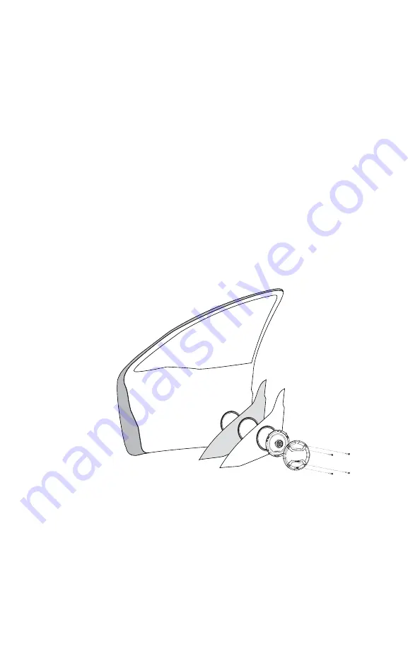
DooR MoUnTInG

When  checking  for  possible  speaker  locations  in  the  doors,  check  the 
operation  of  the  window  and  all  of  the  doors  assemblies .  There  is  also  a 
stabilizer stop bar in between the door and the door jamb . This bar prevents 
the door from opening too far . Pay particular attention to this so you do not 
damage the speaker when you close the door .

figure 1
figura 1
abbildung 1

Stagger the holes for the wiring and use a rubber or

plastic grommet to protect the wire from damage

Figure 3

Front Door 

Body

Front Dash

Kick Panel

Speaker

cut-out

To the

amplifier

or source

unit

3

Inside

of Door

Speaker

cut out

Coaxial

Driver

Dampening Mat

Speaker installed

with no gaps

or air leaks

Dampening on

top of outer

door skin

Door

Panel

Rear/Trunk

of Car

Rear Seat

Grille

Screws

ReaR DeCK MoUnTInG

In rear deck installations, check the operation of the trunk suspension springs 
or tension bars . These tension bars move in the opening and closing of the 
trunk .  You  cannot  be  too  cautious  during  this  part  of  the  installation,  In 
addition, do not locate the speakers too close to the back of the rear deck . 
Mounting  the  far  screws  will  only  be  possible  with  the  removal  of  the  rear 
window .

Summary of Contents for Cobalt CO500

Page 1: ...Coaxial Speaker MODEL CO500 CO570 CO600 CO650 CO690 OWNER S MANUAL ...

Page 2: ...r system The metalized PEI Polyetherimide dome tweeter can be angled on a 360 axis for optimal imaging and sound quality Designed for OEM applications the Cobalt coaxial speakers will fit standard 5 25 6 6 5 round and 5 x 7 6 x 9 oval mounting locations Practice Safe Sound Continuous exposure to sound pressure levels over 100dB may cause permanent hearing loss High powered automotive sound systems...

Page 3: ...ing your installation TOOLS OF THE TRADE Listed are the majority of the tools required to perform the installation Having the proper tools will make the installation much easier Some of these tools are required marking pen needle nose pliers wire crimpers electric drill volt ohm meter opt wire strippers 1 8 drill bit wire cutters assorted tin snips hole saw arbor Phillips screwdriver 43 4 120mm ho...

Page 4: ...e speaker locations in the doors check the operation of the window and all of the doors assemblies There is also a stabilizer stop bar in between the door and the door jamb This bar prevents the door from opening too far Pay particular attention to this so you do not damage the speaker when you close the door Figure 1 Figura 1 Abbildung 1 Stagger the holes for the wiring plastic grommet to protect...

Page 5: ... A hole can be cut either with a pair of metal tin snips or a hole saw corresponding to the size of the speaker listed below 4 3 4 120mm hole saw 5 1 4 5 1 2 140mm hole saw 6 1 2 Step 5 Run the speaker wire to the speakers Make sure to keep wires away from sharp metal or other edges When passing through metal use a protective grommet Step 6 Using the template mark the mounting holes with a pen Ste...

Page 6: ... single channel stereo Figure 4 Figura 4 Abbildung 4 Figure 5 Figura 5 Abbildung 5 The Cobalt speakers can be powered by a head unit or an amplifier Les haut parleurs Cobalt peuvent être alimentés par un récepteur ou un amplificateur Los altavoces Cobalt se pueden alimentar con una unidad principal o un amplificador Die Cobalt Lautsprecher können von einem Autoradio oder einem Verstärker betrieben...

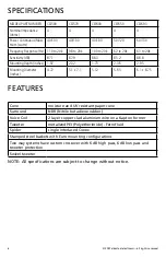
Page 7: ...s 1 97 2 32 1 73 2 36 2 95 Mounting Diameter inches 4 72 5 1 x 7 1 5 12 5 63 6 1 x 8 75 Features Cone moisture and UV resistant paper cone Surround NBR Nitrile butadiene rubber Voice Coil 2 layer copper clad aluminum wire on a Kapton former Tweeter metalized PEI Polyetherimide Ferrofluid Spider single interlaced Conex Stamped steel baskets with Euro mounting configurations Two way systems have cus...

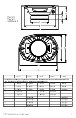
Page 8: ...sions pouces mm Dimensiones plg mm Abmessungen Zoll mm Dimensioni pollici millimetri Dimensões polegadas mm A 1 97 50 2 32 59 1 73 44 2 36 60 2 95 75 B 0 71 18 0 79 20 0 79 20 0 91 23 0 98 25 C 2 76 70 3 15 80 3 15 80 3 15 80 3 94 100 D 4 72 120 5 12 130 5 63 143 E 5 12 130 5 98 152 6 50 165 F 5 04 128 6 06 154 G 5 51 140 6 61 168 H 7 09 180 8 66 220 I 8 66 220 9 17 233 ...

Page 9: ......

Page 10: ...choix Cela donnera souvent d excellents résultats MONTAGE SUR UNE PORTIÈRE Quand vous recherchez une location possible pour installer vos haut parleurs dans les portières vérifiez le fonctionnement de la fenêtre et de tous les mécanismes Vérifiez aussi la barre stabilisatrice entre la portière et son montant Elle empêche la portière de s ouvrir trop grand Faites très attention pour ne pas endommag...

Page 11: ... de la taille correspondant à celle du haut parleur ci dessous Scie cloche 4 3 4 120 mm 5 1 4 Scie cloche 5 5 8 140 mm 6 1 2 Étape 5 Amenez les câbles à leurs haut parleurs Assurez vous de les garder loin de tout bord métallique ou autre aiguisé Pour passer à travers le métal utilisez une rondelle isolante Étape 6 Utilisez le gabarit et un crayon pour marquer les trous de montage Étape 7 Pré perce...

Page 12: ...ontage pouces 4 72 5 1 x 7 1 5 12 5 63 6 1 x 8 75 CARACTÉRISTIQUES Cône Papier résistant à l humidité et aux ultraviolets Boîtier Nitrile Bobine acoustique Fil d aluminium recouvert de 2 couches de cuivre sur manchon Kapton Haut parleur d aigus Polyétérimide métallisé ferrofluide Anneau de cen trage Conex simple entrelacé Paniers en acier matricé avec configuration de montage européen Systèmes bid...

Page 13: ......

Page 14: ... el altavoz en la ubicación de fábrica puede a menudo dar muy buenos resultados MONTAJE EN LA PUERTA Cuando esté buscando posibles ubicaciones de altavoz en las puertas verifique el funcionamiento de las ventanas y de todos los mecanismos de las puertas También hay una barra de tope estabilizadora entre la puerta y la jamba de la puerta Esta barra evita que la puerta se abra demasiado Preste espec...

Page 15: ...ndica abajo Sierra circular de 4 3 4 plg 120 mm altavoz de 5 1 4 plg Sierra circular de 5 1 2 plg 140 mm altavoz de 6 1 2 plg Paso 5 Encamine el cable de altavoz hasta los altavoces Mantenga los cables de altavoz lejos de los bordes afilados de metal u otro material Cuando pase los cables a través de metal ponga en el agujero una arandela de goma protectora Paso 6 Marque los agujeros de montaje co...

Page 16: ...12 5 63 6 1 x 8 75 Características Cono cono de papel resistente a la humedad y los rayos ultravioleta Envolvente Goma de Butadieno de Nitrilo Nitrile Butadiene Rubber NBR Bobina de voz cable de cobre de 2 capas blindado de aluminio en un formador Kapton Tweeter Polieterimida Polyetherimide PEI metalizada Ferrofluido Araña Conex entrelazado de una pieza Canastas de acero troquelado con configuraci...

Page 17: ......

Page 18: ...stellen am besten Der Einbau an diesen Stellen kann oft zu sehr guten Ergebnissen führen TÜREINBAU Wenn Sie mögliche Lautsprechereinbaustellen in den Türen suchen müssen Sie die Funktionen der Fenster und aller Baugruppen der Türen beachten Zwischen der Tür und der Türschwelle befindet sich eine Stabilisator Anschlagleiste Diese Leiste verhindert dass die Tür sich zu weit öffnet Achten Sie darauf ...

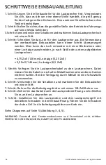
Page 19: ...n aufgelisteten Lautsprechers 4 75 Zoll 120 mm Lochsäge 5 25 Zoll 5 5 Zoll 140 mm Lochsäge 6 5 Zoll 5 Schritt Verlegen Sie die Lautsprecherkabel zu den Lautsprechern Dabei müssen Sie die Kabel von scharfen Metallkanten oder anderen Kanten entfernt halten Bei der Verlegung durch Metall ist eine Schutztülle zu verwenden 6 Schritt Verwenden Sie die Schablone und markieren Sie die Einbaulöcher mit ein...

Page 20: ...hmesser Zoll 4 72 5 1 x 7 1 5 12 5 63 6 1 x 8 75 Eigenschaften Membran Feuchtigkeits und UV beständige Papiermembran Sicke NBR Nitrilgummi Schwingspule Zweischichtiger kupferbeschichteter Aluminiumdraht auf Kap ton Träger Hochtöner Metallisiertes PEI Polyetherimid Ferrofluid Zentriermem bran Conex einfach verknüpft Körbe aus Stahlblech mit Euro Befestigungskonfiguration Zweiwegsysteme haben spezie...

Page 21: ......

Page 22: ...ltoparlante nella sede predisposta in fabbrica spesso si ottengono risultati estremamente desiderabili MONTAGGIO SULLE PORTIERE Quando si valutano le possibili posizioni di montaggio sulle portiere controllare il funzionamento dei finestrini e di tutti i componenti delle portiere stesse Tra portiera e relativo montante c è anche una barra stabilizzatrice di arresto La barra evita un apertura ecces...

Page 23: ...elle misure dell altoparlante indicate di seguito sega a tazza da 4 3 4 120 mm per un altoparlante da 5 1 4 sega a tazza da 5 1 2 140 mm per un altoparlante da 6 1 2 Fase 5 passare il filo fino all altoparlante Accertarsi di tenere i fili lontani da bordi od oggetti di metallo taglienti Quando si passano i fili in un foro in un oggetto metallico usare un anello di protezione Fase 6 usando la dima ...

Page 24: ...ci 4 72 5 1 x 7 1 5 12 5 63 6 1 x 8 75 Caratteristiche Cono Cono in carta resistente all umidità e ai raggi ultravioletti Surround NBR gomma nitrile butadiene Bobina mobile Doppio strato di filo di alluminio rivestito di rame su un supporto in Kapton Tweeter PEI Polieterimide metallizzato Ferrofluido Centratore Conex intrecciato Telai in acciaio stampato con configurazioni di montaggio europee Gli...

Page 25: ......

Page 26: ...em ser a solução mais adequada Colocar os alto falantes nas posições definidas pela fábrica pode muitas vezes produzir resultados muito satisfatórios INSTALAÇÃO NAS PORTAS Ao verificar os possíveis locais para instalação dos alto falantes nas portas estude como funcionam os vidros e todos os componentes das portas Existe também uma barra de limitação estabilizadora entre a porta e o batente Ela ev...

Page 27: ...o alto falante descrito abaixo Serra copo de 120 mm 4 3 4 para instalação do alto falante de 133 mm 5 1 4 Serra copo de 140 mm 5 1 2 para instalação do alto falante de 165 mm 6 1 2 Etapa 5 Passe o cabo para caixa acústica até os alto falantes Mantenha os cabos afastados de superfícies de metal ou outras bordas afiadas Use um olhal de proteção ao passar o cabo através de metal Etapa 6 Usando o mode...

Page 28: ...de instalação polegadas 4 72 5 1 x 7 1 5 12 5 63 6 1 x 8 75 Características Cone Cone de papel resistente à umidade e à radiação ultravioleta Surround Borracha nitrílica NBR Bobina móvel Fio de alumínio revestido de cobre de duas camadas em um copo Kapton Tweeter Polieterimida PEI metalizada Ferrofluido Aranha Conex entrelaçado simples Carcaças de aço estampado com configurações de instalação euro...

Page 29: ...er modification of existing equipment or Product which has been opened or tam pered for any reason Units which are found to be damaged by abuse resulting in thermally damaged voice coils are not covered by this warranty but may be replaced at the absolute and sole discretion of Directed Unit must be returned to Directed DO NOT RETURN THE ENTIRE ENCLOSURE THE UNIT ENCLOSURE IS COV ERED BY A SEPARAT...

Reviews: