background image

© 2007 directed electronics—all rights reserved  

7

INSTALLING THE CROSSOVER

Step 1:  Find  a  location  for  the  crossover  away  from  any  factory  or  after  
 

market  electrical  wires.    It  is  recommended  to  mount  the  passive  


crossover  close  to  the  amplifier.    In  the  event  you  decide  to  upgrade  


and bi-amplify the system, mounting the passive crossover close to the  


amplifier would simplify the installation upgrade.

Step 2:  Remove top cover of crossover housing.  Don’t lose it.

Step 3:  Mark with a marking pen the two mounting holes.

Step 4:  Remove crossover and pre-drill mounting holes using a 1/8” drill bit.

WARNING:


Check  for  clearance  of  window  mechanisms  and  electrical  wires 


BEFORE  you drill.

Step 5:  Mount the crossover using the supplied #8 screws.

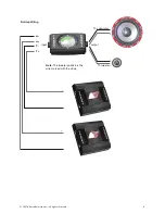
Step 6:  Connect the wires.  Make sure the speaker wires for the mid/woofer go to the  
 

woofer  output  and  the  tweeter  to  the  tweeter  output.  


Be 

sure 

to 

observe 

the 

correct 

polarity. 

Changing 

the  


polarity  of  the  tweeter  may  be  necessary  for  optimum  sound  quality.

Step 7:  Re-install the crossover cover.

Summary of Contents for HCCA 5.2

Page 1: ...HCCA 5 2 HCCA 6 2...

Page 2: ...high performance components are built with 4 ohm voice coils to get the most out of your amplifier The components are available in a standard 5 1 4 and 6 1 2 sizes to fit most applications We at Orion...

Page 3: ...ssover to amplifier 1 Mounting template 2 Grills Mounting screws INSTALLATION The performance of the HCCA Component Loudspeaker is directly proportional to the quality of installation Care taken durin...

Page 4: ...8 Hole Saw 6 1 2 woofer install 4 3 4 Hole Saw 5 1 4 mid woofer install 2 or 2 1 8 Hole Saw for flush mount tweeter installation FINDING SPEAKER MOUNTING LOCATIONS Choosing the correct speaker locatio...

Page 5: ...perly An uneven mounting surface can damage the driver Step 2 Check to make sure the space you have chosen for the speaker will not interfere with the operation of the vehicle Step 3 Using the supplie...

Page 6: ...echanisms and electrical wires BEFORE you drill Step 4 Drill the larger off center hole using a 3 8 drill bit insert a grommet and route the speaker wire from the crossover through the grommet Step 5...

Page 7: ...e cut either with a pair of metal tin snips or a 2 hole saw for soft materials or 2 1 8 hole saw for hard materials WARNING Check for clearance of window mechanisms and electrical wires BEFORE you dri...

Page 8: ...top cover of crossover housing Don t lose it Step 3 Mark with a marking pen the two mounting holes Step 4 Remove crossover and pre drill mounting holes using a 1 8 drill bit WARNING Check for clearan...

Page 9: ...on opposite ends of the plug to make the wiring easier Parallel wiring is also probably the most popular wiring method The bi wire bi amp selection is for using two separate channels for powering the...

Page 10: ...2007 directed electronics all rights reserved _ _ _ _ Bi Amp Wiring Note The tweeter positive is the wire marked with the stripe To tweeter To subwoofer w w T T output input...

Page 11: ...Cone paper Kevlar blend moisture and UV resistant Surround polyester foam Magnet Neodymium Voice Coil CCAW wire copper clad aluminum wire for best power handling and light weight moving parts Tweeter...

Page 12: ...abuse resulting in thermally damaged voice coils are not covered by this warranty but may be replaced at the absolute and sole discretion of Directed Unit must be returned to Directed postage pre pai...

Reviews: