background image

50

MIS-4220 / MIS-4220R / MIS-4230

51

Infinitely Expandable 

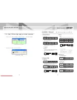
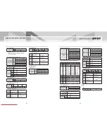
Protocol Example

3. 

3.1 Send Command

3.1.1 Multi Scale Control

  Multi Scale Command  


ƒ

(PDP ID = 3, Source = PC, Configuration = 2x2)

Multi

Scale

(19byte)

Command

PDP ID

Sub Command

0x36 0x3B 0x34 0x3D

0x30 0x33

0x34 0x3D 0x37 0x33

Data

End

Source

Width

Height

Position

0x37 0x30

0x30 0x32

0x30 0x32

0x30 0x33

0x0d


Index

Converted Data

Send Data

Command

0x36, 0x3B, 0x34, 0x3D

PDP ID

"3": 0x30, 0x33

0x30, 0x33

Sub Command

0x34, 0x3D, 0x37, 0x33

Source

PC(0x70): 0x37, 0x30

0x37, 0x30

Width

"2": 0x32, 0x32

0x30, 0x32

Height

"2": 0x32, 0x32

0x30, 0x32

Position

ID is "3", so position value 

"3": 0x30, 0x33

0x30, 0x33


3.1.2 PDP Control

Power On Command (PDP ID = 1)


ƒ

Power On

(11byte)

Command

PDP ID

Sub Command

End

0x36 0x3B 0x34 0x3D 0x30 0x31 0x35 0x32 0x36 0x3E

0x0d


Index

Converted Data

Send Data

Command

0x36, 0x3B, 0x34, 0x3D

PDP ID

"1": 0x30, 0x31

0x30, 0x31

Sub Command

0x35, 0x32, 0x36, 0x3E


3.1.3 Get Data Control

Get WhiteBalance Version Command(PDP ID = 1)


ƒ

Get

White

Balance

(11byte)

Command

PDP ID

Sub Command

End

0x36 0x3B 0x34 0x3D 0x30 0x31 0x34 0x37 0x35 0x34

0x0d


Index

Converted Data

Send Data

Command

0x36, 0x3B, 0x34, 0x3D

PDP ID

"1": 0x30, 0x31

0x30, 0x31

Sub Command

0x34, 0x37, 0x35, 0x34

3.1.4 WhiteBalance Control

 Graphic Data Brightness Command  


ƒ

(PDP ID = 1, Data = 50)

Graphic

Data

Brightness

(17byte)

Command

PDP ID

Sub Command

0x36 0x3B 0x34 0x3D 0x30 0x31

0x34 0x37 0x35 0x34

Data

End

0x33 0x32

0x0d


Index

Converted Data

Send Data

Command

0x36, 0x3B, 0x34, 0x3D

PDP ID

"1": 0x30, 0x31

0x30, 0x31

Sub Command

0x34, 0x37, 0x36, 0x31

Data

"50"(0x32): 0x33, 0x32

0x33, 0x32

3.1.5 BIC Control

 BIC Local Data Send Command (PDP ID = 1)


ƒ

BIC

Local

Data

(17byte)

Command

PDP ID

Sub Command

0x36 0x3B 0x34 0x3D

0x30 0x31

0x34 0x32 0x35 0x3C

Data

End

0x30 0x34 0x30 0x31 0x30 0x34

0x0d


Index

Converted Data

Send Data

Command

0x36, 0x3B, 0x34, 0x3D

PDP ID

"1": 0x30, 0x31

0x30, 0x31

Sub Command

0x34, 0x32, 0x35, 0x3C

Data

0x30, 0x34, 0x30, 0x31, 

0x30, 0x34

3.2 Receive Command

3.2.1BIC Control

BIC Local Data Receive Command (PDP ID = 1)


ƒ

BIC

Local

Data

(25byte)

Command

PDP ID

Sub Command

0x36 0x3B 0x34 0x3E

0x30 0x31

0x34 0x32 0x35 0x3C

Data

End

0x30 0x34 0x30 0x31 0x30 0x34

Receive 8 byte

0x0d

Index

Converted Data

Send Data

Command

0x36, 0x3B, 0x34, 0x3D

PDP ID

"1": 0x30, 0x31

0x30, 0x31

Sub Command

0x34, 0x32, 0x35, 0x3C

Data

0x30, 0x34, 0x30, 0x31, 

0x30, 0x34

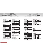
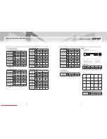
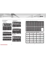
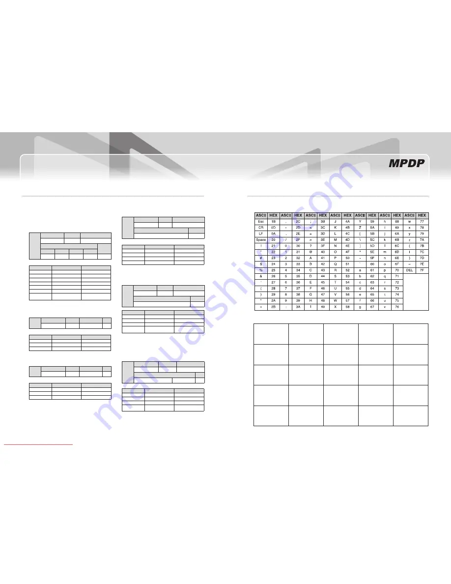
※attachment : aSCii to HEX Conversion Table

※Hex code value according to Set iD 

iD 1

id[0] = 0x30
id[1] = 0x31

iD 2

id[0] = 0x30
id[1] = 0x32

iD 3

id[0] = 0x30
id[1] = 0x33

iD 4

id[0] = 0x30
id[1] = 0x34

iD 5

id[0] = 0x30
id[1] = 0x35

iD 6

id[0] = 0x30
id[1] = 0x36

iD 7

id[0] = 0x30
id[1] = 0x37

iD 8

id[0] = 0x30
id[1] = 0x38

iD 9

id[0] = 0x30
id[1] = 0x39

iD 10

id[0] = 0x30
id[1] = 0x3A

iD 11

id[0] = 0x30
id[1] = 0x3B

iD 12

id[0] = 0x30

id[1] = 0x3C

iD 13

id[0] = 0x30

id[1] = 0x3D

iD 14

id[0] = 0x30
id[1] = 0x3E

iD 15

id[0] = 0x30
id[1] = 0x3F

iD 16

id[0] = 0x31
id[1] = 0x30

iD 17

id[0] = 0x31
id[1] = 0x31

iD 18

id[0] = 0x31
id[1] = 0x32

iD 19

id[0] = 0x31
id[1] = 0x33

iD 20

id[0] = 0x31
id[1] = 0x34

iD 21

id[0] = 0x31

id[1] = 0x35

iD 22

id[0] = 0x31

id[1] = 0x36

iD 23

id[0] = 0x31

id[1] = 0x37

iD 24

id[0] = 0x31

id[1] = 0x38

iD 25

id[0] = 0x31

id[1] = 0x39

(MPDPD 5X5)

Downloaded From TV-Manual.com Manuals

Summary of Contents for MIS-4220

Page 1: ...Multi Plasma display model only 2008 03 05 A revolutionary MPDP Infinitely Expandable MPDP User s Manual MIS 4220 MIS 4220R MIS 4230 A revolutionary MPDP Infinitely Expandable MPDP Address 257 Gongdan dong Gumi si Gyeongsangbuk do Korea Tel 82 2 6678 8523 Fax 82 2 6678 8599 ORION PDP CO LTD www oriondisplay net Downloaded From TV Manual com Manuals ...

Page 2: ...1 BIC Intervals and effect 41 5 14 Orion PDP Home Page logon and Version information 42 6 MSCS Protocol 43 Attachment ASCII to HEX Conversion Table 51 Hex code value according to Set ID 51 7 Other tips 52 7 1 Before calling for service 52 7 2 About Plasma display panel 53 8 Applicable signals 54 8 1 DVD DTV 54 8 2 PC DVI 54 9 Specifications MIS 4220 4220R 4230 55 If you fail to comply with the reg...

Page 3: ...s ground or floor Please do not lean over the PDP It may damage the bottom part of the PDP If you need to lay down PDP as face down position please use shock absorbing pads under the PDP Please do not lean over the PDP toward the edge part It may damage the edge part of the PDP If you need to lay down PDP as face up position please be cautious for falling objects on the surface of the PDP PANEL PA...

Page 4: ...ful not to touch the bottom part of the panel when you put down the panel When you carry MPDP with flatbed manner please hold handles on the back and lower part of the back Please be careful not to touch the bottom part of the panel when you put down the panel Please do not touch the panel with your hand Please see page 8 for unpack and handle assembly PANEL MASTER FRAME MIS 4220 MIS 4230 MIS 4220...

Page 5: ...oduct It may cause electric shock or fire Do not touch product s front surface with hand Otherwise the image quality can be lowered If it operates abnormally stop using it immediately Please refer to a specialized construction company for installing stand or wall mount unit Otherwise damage or injury may be caused Avoid any action to damage the power cord or power plug It may cause fire or electri...

Page 6: ...product s back side 2 It needs two people to carry or install this product Please hold the handles in the back and the front bottom part at the same time Please do not grab the panel but grab bottom of master frame when you carry or install the products Please use gloves when you carry or install the products Attention Do not remove the panel protection pad until a set is completely installed on a...

Page 7: ...or adequate ventilation and technical service Please do not install our product at following locations to protect the product and y y prevent possible malfunction Places of vibration or shock PDP set may fall and damaged Next or near to Sprinkler sensors The sensors may detect heat from a set and sprinkler can be activated Around high voltage power lines Noise from the power line may affect screen...

Page 8: ...icture for adequate ventilation and technical service Please do not install our product at following locations to protect the product and y y prevent possible malfunction Places of vibration or shock PDP set may fall and damaged Next or near to Sprinkler sensors The sensors may detect heat from a set and sprinkler can be activated Around high voltage power lines Noise from the power line may affec...

Page 9: ...number If you do not disconnect power cord the PDPs maintain the previous ID and it may cause malfunction PDP ID 01 0 1 2 3 4 5 6 7 8 9 0 1 2 3 4 5 6 7 8 9 PDP ID 15 10 digit single digit 10 digit single digit LED Indication y y LED ON OFF LED Indication Description 0 1 2 3 4 5 6 7 8 9 0 1 2 3 4 5 6 7 8 9 M ON M STB FAN S ON No Power 0 1 2 3 4 5 6 7 8 9 0 1 2 3 4 5 6 7 8 9 M ON M STB FAN S ON Inte...

Page 10: ... MPDP with a PC If you do not have Com Port you need to use an USB converter for RS 232 Depending y y on manufacturers or models converters may cause malfunction PC 0 1 2 3 4 5 6 7 8 9 0 1 2 3 4 5 6 7 8 9 RS 232C VIDEO IN OUT IN OUT S VIDEO IN OUT COMPONENT IN OUT Y Pb Pr DVI D PC IN IN OUT OUT ID SELECT M ON M STB S ON FAN PDP ID 1 ID switch must be set as ID 1 y y for one set use 0 1 2 3 4 5 6 7...

Page 11: ...UT COMPONENT IN OUT Y Pb Pr DVI D PC IN IN OUT OUT ID SELECT M ON M STB S ON FAN VCR Connection PC MSCS to control MPDP VCR RS 232C Maximum 15m S Video connection Maximum 5m Video connection Maximum 5m PDP ID 1 ID switch must be set as ID 1 y y for one set use 0 1 2 3 4 5 6 7 8 9 0 1 2 3 4 5 6 7 8 9 Downloaded From TV Manual com Manuals ...

Page 12: ...mum 15m Component connection Maximum 5m PDP ID 1 ID switch must be set as ID 1 y y for one set use 0 1 2 3 4 5 6 7 8 9 0 1 2 3 4 5 6 7 8 9 According to manufacturers the indication of DVD Component output port may vary Y PB PR Y B Y R Y or Y CB CR Component Input ports You can get better image quality by connecting DVD player to component input ports as below Component ports of the set Y Pb Pr Vid...

Page 13: ...NT IN OUT Y Pb Pr DVI D PC IN IN OUT OUT ID SELECT M ON M STB S ON FAN 0 1 2 3 4 5 6 7 8 9 0 1 2 3 4 5 6 7 8 9 RS 232C VIDEO IN OUT IN OUT S VIDEO IN OUT COMPONENT IN OUT Y Pb Pr DVI D PC IN IN OUT OUT ID SELECT M ON M STB S ON FAN 0 1 2 3 4 5 6 7 8 9 0 1 2 3 4 5 6 7 8 9 RS 232C VIDEO IN OUT IN OUT S VIDEO IN OUT COMPONENT IN OUT Y Pb Pr DVI D PC IN IN OUT OUT ID SELECT M ON M STB S ON FAN 0 1 2 3...

Page 14: ...N OUT RS 232C IN OUT RS 232C IN OUT RS 232C IN OUT RS 232C IN OUT RS 232C IN OUT RS 232C IN OUT RS 232C IN OUT RS 232C IN OUT RS 232C IN OUT RS 232C IN OUT RS 232C IN OUT RS 232C IN OUT RS 232C IN OUT RS 232C IN OUT RS 232C IN OUT RS 232C IN OUT RS 232C IN OUT RS 232C Distributor RS 232C control PC ID 1 ID 4 ID 7 ID 2 ID 5 ID 8 ID 3 ID 6 ID 9 RS 232C IN OUT RS 232C IN OUT RS 232C IN OUT RS 232C IN...

Page 15: ... 2 3 4 5 6 7 8 9 0 1 2 3 4 5 6 7 8 9 0 1 2 3 4 5 6 7 8 9 0 1 2 3 4 5 6 7 8 9 0 1 2 3 4 5 6 7 8 9 0 1 2 3 4 5 6 7 8 9 0 1 2 3 4 5 6 7 8 9 0 1 2 3 4 5 6 7 8 9 0 1 2 3 4 5 6 7 8 9 0 1 2 3 4 5 6 7 8 9 0 1 2 3 4 5 6 7 8 9 0 1 2 3 4 5 6 7 8 9 0 1 2 3 4 5 6 7 8 9 0 1 2 3 4 5 6 7 8 9 0 1 2 3 4 5 6 7 8 9 0 1 2 3 4 5 6 7 8 9 0 1 2 3 4 5 6 7 8 9 0 1 2 3 4 5 6 7 8 9 0 1 2 3 4 5 6 7 8 9 0 1 2 3 4 5 6 7 8 9 0 1...

Page 16: ...IDEO Gray 5 3 Setting Com Port Com Port connects or disconnects the communication between PC and MPDP y y Connect MPDP to PC Com Port via RS 232C cable y y Go to MSCS Menu Communication and set Com Port Click Connect using mouse or press Ctrl C y y using keyboard In order to disconnect communication click Disconnect using mouse or press Ctrl D using keyboard y y When you use USB to RS232C converte...

Page 17: ...Screen Configuration Setting 1 2 3 PC PC PC PC PC PC PC PC PC 5 6 MSCS Instruction Check ALL PDP to send data to all connected MPDP regardless of ID y y In order to control power of specific MPDP use Power On Off button after selecting the specific MPDP y y 5 7 ID Setting ID of MSCS Multi Screen Control System is set automatically y y In order to transmit data to chosen MPDP ID of Screen Configura...

Page 18: ... 2 3 5 8 Configuration of various modes You can configure various input sources as you want y y DVI PC PC PC PC PC PC PC PC DVI PC PC PC DVD PC PC PC DVD Click Play button on the main image of MSCS or scroll using mouse to return to initial image Select a desirable input source in Select Input Select DVI in Select Input Select screens with left button of mouse and drag from the first screen Select...

Page 19: ...is from 10 seconds to 1 hour 1 2 PC PC PC PC PC PC PC PC PC PC PC PC PC PC PC PC PC PC Save various screen configurations in the same way Click Slide Start to display saved screen configurations Saved screen configurations are displaying for preset time Check Repeat to display saved configuration repeatedly Click Stop button to end Slide Control 4 3 5 To view the slide form click List Box of saved...

Page 20: ...rd Tracking Manual window enables users to set Frequency Phase y y LineStart and PixelStart When Tracking Manual window is on display users cannot display y y Picture Control window Even when Tracking Manual window is on display selecting ID is y y available by clicking right button of mouse Refer to 5 5 PDP ID Setting Detail adjustment steps are as follows y y 1 Tune Phase until the vertical line...

Page 21: ...ion On BYPASS Mode 2 Deactivate BIC function but BIC board keeps recording burn in history BIC function Off 2 Additional compensation REGENERATION Mode 1 Compensate burn in effect by displaying a reversal image of the current burn in image Anti Image Sticking 2 Mode In case you find serious Burn in effect in a certain area select Anti Image Sticking Mode White Stripe pattern scans whole screen to ...

Page 22: ...operty of phosphor material each panel may show slightly different characteristics from each other Therefore it is important to improve compensation efficiency in early stage using 1 Deterioration function and 2 Phosphor update function However such work is only needed when Burn in image is developed to a disturbing level It should be done after one month from the date of initial operation after i...

Page 23: ...from PC to PDP fixed 4byte Refer to the Data format shown in 6 1 Protocol Form Receive From PDP Receive From PDP ASCII k 0x6B N 0x4E HEX 0x36 0x3B 0x34 0x3E Starting code for Send Respond from PDP to P fixed 4byte Refer to the Data format shown in 6 1 Protocol Form 0X6B 0X06 0X06 0X30 0X0B 0X30 0X60 0X0B Real Data Send Data 0X36 0X3B 2 2 PDP ID Format Send Data is 2byte Refer to the Data format sh...

Page 24: ... 0x52 R 0x52 HEX 0x35 0x32 0x35 0x32 Software Reset Position Command Position Up ASCII P 0x50 u 0x75 HEX 0x35 0x30 0x37 0x35 Position Down ASCII P 0x50 d 0x64 HEX 0x35 0x30 0x36 0x34 Position Left ASCII P 0x50 l 0x6C HEX 0x35 0x30 0x36 0x3C Position Right ASCII P 0x50 r 0x72 HEX 0x35 0x30 0x37 0x32 Position Reset ASCII P 0x50 S 0x53 0x35 0x30 0x35 0x33 Component SVIDEO Composite Video Input screen...

Page 25: ...EX 0x34 0x37 0x37 0x33 Graphic Data Gain Blue ASCII G 0x47 t 0x74 HEX 0x34 0x37 0x37 0x34 Graphic Data Offset Red ASCII G 0x47 u 0x75 HEX 0x34 0x37 0x37 0x35 Graphic Data Offset Green ASCII G 0x47 v 0x76 HEX 0x34 0x37 0x37 0x36 Graphic Data Offset Blue ASCII G 0x47 w 0x77 HEX 0x34 0x37 0x37 0x37 Command for controlling White Balance for PC and DTV Video Data Command Video Data Bright ness ASCII V ...

Page 26: ...13 Color Temp Data 14 Data 15 Auto Power Data 16 Data 21 Firmware Version Refer to the Data format shown in 6 1 Protocol Form Index Length Note PDP ID 2byte 1 0x30 0x31 10 0x30 0x3A 99 0x36 0x33 Input Source 2byte 14 DVI 12 PC 13 DTV 7 DVD 5 SVIDEO 2 VIDEO Standard Table 2byte 1 640x480x60 2 640x480x85 3 800x600x56 4 800x600x60 5 800x600x75 6 800x600x85 7 853x480x60 8 1024x768x60 9 1024x768x70 10 ...

Page 27: ...mmand 0x36 0x3B 0x34 0x3D PDP ID 1 0x30 0x31 0x30 0x31 Sub Command 0x34 0x37 0x36 0x31 Data 50 0x32 0x33 0x32 0x33 0x32 3 1 5 BIC Control BIC Local Data Send Command PDP ID 1 BIC Local Data 17byte Command PDP ID Sub Command 0x36 0x3B 0x34 0x3D 0x30 0x31 0x34 0x32 0x35 0x3C Data End 0x30 0x34 0x30 0x31 0x30 0x34 0x0d Index Converted Data Send Data Command 0x36 0x3B 0x34 0x3D PDP ID 1 0x30 0x31 0x30...

Page 28: ...henomena caused by characteristics of the plasma display panel Since it is not a fault you may continue to use the product Black or twinkling spots on the screen Although the plasma display panel is manufactured with high precision y y technology there may exist black or twinkling spots on the screen Since it is not a fault you may continue to use the product Burn In effect Displaying static image...

Page 29: ...360W Plasma display panel 42 inch 16 9 Aspect Ratio Contrast ratio 10 000 1 Dark Room Brightness 1 000 cd W O Film Front filter AGAR Anti Glare Anti Reflection Number of pixels 853 H X 480 V Seam gap In case of multi formation 4mm Environmental condition Temperature 0 C 35 C Humidity 20 70 Signal Video signal NTSC PAL SECAM PC signal SVGA WVGA XGA SXGA WXGA UXGA Frequency Horizontal Frequency 15 5...

Page 30: ...and specification can be changed for quality improvement without prior notice 924 6 mm 0 2 75 4mm 0 5 528 8mm 1 521 8mm 0 2 336 0mm 1 Model Name MIS 4220R Power supply 100 240V AC 50 60Hz Power consumption Average Typical 300W Max 360W Plasma display panel 42 inch 16 9 Aspect Ratio Contrast ratio 10 000 1 Dark Room Brightness 1 000 cd W O Film Front filter AGAR Anti Glare Anti Reflection Number of...

Reviews: