14
MIS-4220 / MIS-4220R / MIS-4230
15
Infinitely Expandable
3. guidance for Users
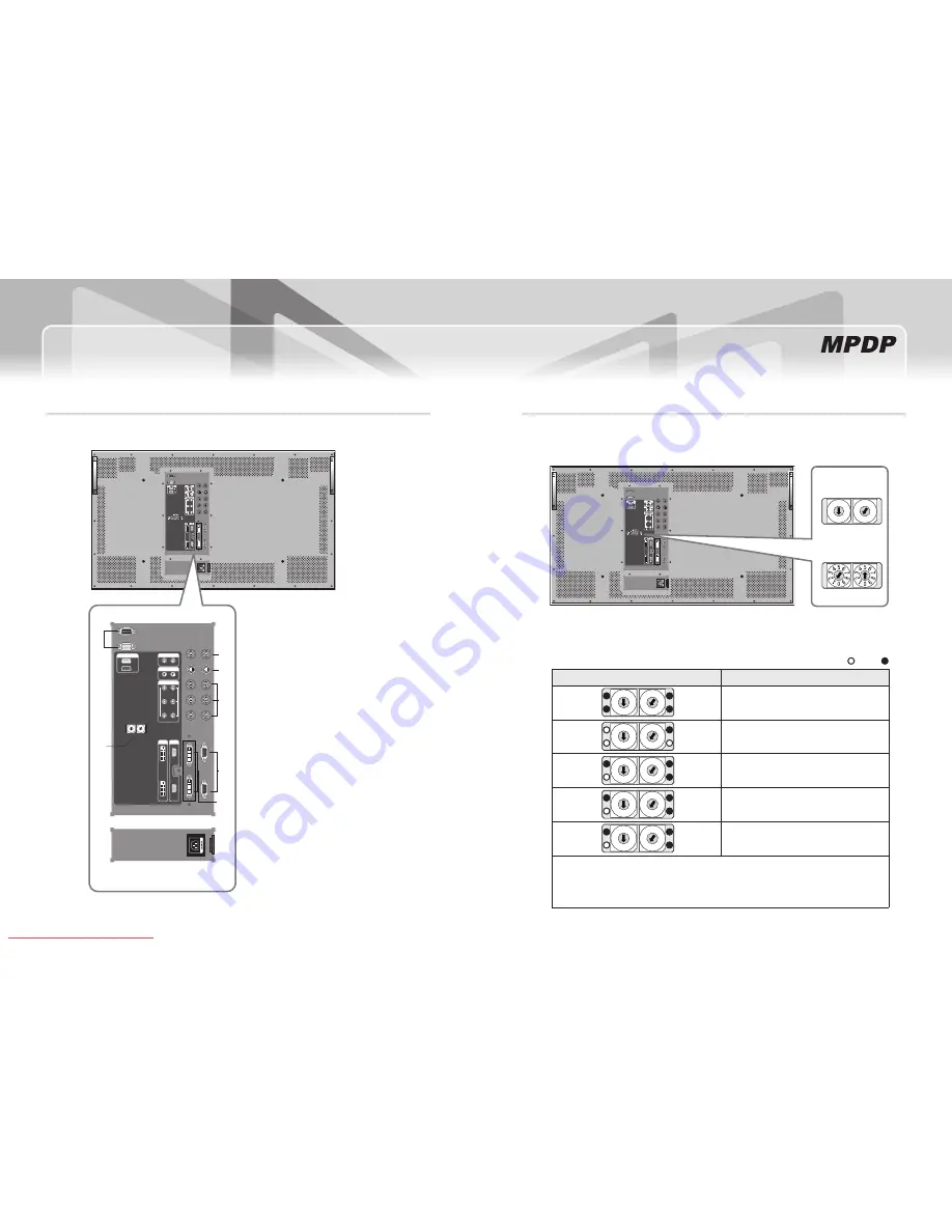
input/Output Terminals
01
2
3
4 5 67
8
9
01
2
3
4 5 67
8
9
RS-232C
VIDEO
IN
OUT
IN
OUT
S-VIDEO
IN
OUT
COMPONENT
IN
OUT
Y
Pb
Pr
DVI-D
PC
IN
IN
OUT
OUT
ID SELECT
M-ON
M-STB
S-ON
FAN
❶
❷
❸
❹
❺
❻
❼
❽
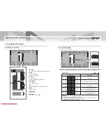
1. RS-232C
MPDP Control, Firmware Upgrade, 9pin D-sub
2. Video
Composite Signal
NTSC, PAL, SECAM
3. S-Video
S-Video Signal
NTSC, PAL, SECAM, 4pin Mini Din
4. Component
DVD Signal
DTV - YPbPr Signal
5. PC
Computer RGB Analog Signal, D-sub 15pin
6. DVI-D
TMDS Signal
7. ID Switch
Set ID Switch
8. AC Input
AC 100V ~240V, 50/60Hz
Set iD Switch Setting
Example of ID Switch setting
y
- You can set ID with 2 rotary switches as shown in the following figure.
※ When you set or change PDP iD, please disconnect power cord before setting or changing the iD number.
if you do not disconnect power cord, the PDPs maintain the previous iD and it may cause malfunction.
[PDP ID 01]
01
2
3
4 5 67
8
9
01
2
3
4 5 67
8
9
[PDP ID 15]
10 digit single digit
10 digit single digit
LED indication
y
LED ON OFF
LED Indication
Description
01
2
3
4 5 67
8
9
01
2
3
4 5 67
8
9
M-ON
M-STB
FAN
S-ON
No Power.
01
2
3
4 5 67
8
9
01
2
3
4 5 67
8
9
M-ON
M-STB
FAN
S-ON
Internal System Check after Power on.
01
2
3
4 5 67
8
9
01
2
3
4 5 67
8
9
M-ON
M-STB
FAN
S-ON
System ready.
01
2
3
4 5 67
8
9
01
2
3
4 5 67
8
9
M-ON
M-STB
FAN
S-ON
Power ON by MSCS Program.
(M-ON and S-ON LED will sequentially blink
with 1 second interval.)
01
2
3
4 5 67
8
9
01
2
3
4 5 67
8
9
M-ON
M-STB
FAN
S-ON
Power Off by MSCS Program.
(System ready).
Remark)
M-ON(Master-ON) : IP Board Master Power On.
FAN : FAN POWER ON, IF Red LED on IP board is turned on, please check FANs.
M-STB(Master-
Stand By
) : IP Board Master Ready
S-ON(Slave-ON) : IP Board Slave Ready
Downloaded From TV-Manual.com Manuals


