background image

Zone

Zone

INSTALLATION & WIRING


VCB-X Controller Field Technical Guide

32

Digital Compressor Unloader Wiring

  Digital Compressor Unloader

The Digital Compressor Unloader uses a  solenoid unloader as the 
capacity control method. The unloader solenoid is energized in an on/
off pattern to deliver the capacity needed by the digital compressor 
to achieve setpoint.

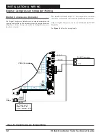
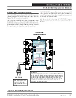
Figure 18:     Digital Compressor Unloader Wiring

The Unloader Solenoid output is a triac output. The maximum 
continuous solenoid load is 0.5A and the peak inrush current is 6A.

Only (1) Digital Compressor can be controlled with the VCB-X 
Controller. 

See 

Figure 18

 below for wiring details.

24VAC

GND

Line
Voltage

Size Transformer For
Correct Total Load.
VCB-X Controller = 8 VA

DAMAGED

E-BUS

EXPANSION

E-BUS

EXPANSION

24 VAC

INPUT

VCB-X Controller

GND

+

_

GND

UNLOAD

Digital Compressor

24 VAC

Summary of Contents for OE335-26B-VCBX-A

Page 1: ...Controller Field Technical Guide VCB X Controller Code SS1051 Version 2 0 and up Requires Modular Service Tool SD Code SS1063 Version 1 0 and up Requires System Manager TS II Code SS7002 Version 2 0 a...

Page 2: ...Temperature Sensor 39 Leaving Water Temperature Sensor 40 Building Static Pressure Sensor 42 Head Pressure Transducer 43 Building Pressure Control Output 44 Chilled Water Valve Actuator 45 Condenser...

Page 3: ...cation 63 Heating 65 Ventilation 65 Off Mode 65 Remote Contact Control 66 Space Sensor Operation 66 IAQ CO2 Control Operation 66 Morning Warm Up Cool Down 66 Single Zone VAV 67 Supply Air Temperature...

Page 4: ...EM1 Expansion Module LED Locations 79 LED Operation 80 APPENDIX A 81 System Configurations 81 Space Outdoor Air or Return Air Temperature Sensor Testing 85 Copeland Discharge Thermistor Temperature Se...

Page 5: ...r If the application requires more inputs and or outputs the optional expansion modules are available to provide for additional analog binary or digital inputs and outputs as required Other features o...

Page 6: ...of modulating Heating or Cooling sources Make Up Air Unit The VCB X can be configured for 100 Outdoor Air control for Make Up Air All HVAC Modes are determined from the Outdoor Air Sensors The Outdoo...

Page 7: ...E217 02 A E BUS Digital Room Sensor LCD Display Temp RH OE217 03 A E BUS Digital Room Sensor No LCD Display Temp RH OE217 04 A E BUS Horizontal Outside Air Temperature RH Sensor OE265 15 A OE265 15 C...

Page 8: ...display of certain status and setpoints The OE217 03 is used with the VCB X Controller for room air temperature and humidity sensing applica tions Uses EBC E BUS cable Display Override OVERRIDE ALARM...

Page 9: ...Controller If a longer EBC cable is required it must be ordered separately Page 28 OE265 16 A E BUS Vertical Outdoor Air Temperature Humidity Sensor Used for outdoor temperature and humidity sensing...

Page 10: ...ications Includes Static Pressure Pick up Tube with 1 ft length of FRP tubing gasketed mounting bracket and screws Page 38 OE230 OE231 Duct Temperature Sensor 6 Probe Duct Temperature Sensor 12 Probe...

Page 11: ...mmunications see OE415 02 IP Module Kit Includes CommLink 5 6 ft long USB cable and 120 24 VAC power sup ply Required on all networked systems or if direct computer or remote computer connection is re...

Page 12: ...Controllers together with EBC E BUS cables of varying lengths Includes E BUS Adapter Hub and 1 5 foot EBC E BUS cable Pages 28 29 OE437 03 Communication Surge Protector Kit Used to isolate power surge...

Page 13: ...additional input is available for communicating sensors available from WattMaster Controls The GPC XP also supports 8 wet contact binary inputs which can be configured for either normally open or norm...

Page 14: ...BIN1 BIN2 BIN3 BIN4 BINARY INPUTS 1uF 1uF 1uF 1002 1002 1002 1002 1002 1002 1002 1002 3650 2201 2201 1002 3650 ADDRESS 01uF OFF 24VAC UNLOAD 3650 3650 3650 3650 3650 12V GND 5V GND 2 1 485 DRV BACNET...

Page 15: ...002 1002 3650 R4 1002 R5 1002 J1 C26 OPTIONS R2 47 47 1001 1001 3650 3650 3650 5621 5621 5621 5621 YS102482 REV1 5 63 5 00 2 67 0 62 2 05 4 10 0 20 5 83 5 34 1 49 DEPTH WattMaster Label L102100 A Rev...

Page 16: ...4 D201 L20 YS102484 REV 1 OFF 1002 1002 3650 3650 3650 3650 3001 3001 3001 4751 4751 4751 22pF 22pF 1uF 1002 1002 1002 1002 1002 1002 1002 01uF 1 49 DEPTH GND GND 24 VAC ANALOG INPUT TB BINARY INPUT T...

Page 17: ...SERIAL POWER C213 R211 R212 R214 C214 R213 TB10 SW1 R44 R43 R42 R41 J1 R40 D6 TB3 TB2 TB1 R8 D3 RLY9 RLY10 RLY11 RLY12 RLY COM MADE IN USA RLY COM RLY COM RLY1 RLY2 RLY3 RLY4 RLY8 RLY7 RLY6 RLY5 24VAC...

Page 18: ...U2 TB7 R68 T SH R 3650 1uF C81 X ENTER UP DOWN ALARM CANCEL RELAY CONTACT RATING IS 1 AMP MAX 24 VAC RS 485 COMM LOOP WIRE R TO R T TO T SHLD TO SHLD 24 VAC POWER ONLY WARNING POLARITY MUST BE OBSERV...

Page 19: ...also be used 8 Before applying power to the VCB X Controller be sure to recheck all wiring connections and terminations thoroughly Important Wiring Considerations General Correct wiring of the VCB X...

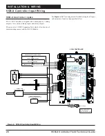
Page 20: ...OBSERVED OR THE CONTROLLER WILL BE DAMAGED www aaon com www orioncontrols com VCB X CONTROLLER Orion No OE335 26B VCBX AAON V28940 AAON Coil J00142 ANALOG INPUTS AI1 SPC SPACE TEMP SENSOR AI2 AI3 AI4...

Page 21: ...EHEAT 19 EXHAUST FAN 20 HEAT WHEEL X ENTER UP DOWN ALARM CANCEL RELAY CONTACT RATING IS 1 AMP MAX 24 VAC RS 485 COMM LOOP WIRE R TO R T TO T SHLD TO SHLD 24 VAC POWER ONLY WARNING POLARITY MUST BE OBS...

Page 22: ...OVERRIDE ALARM E BUS Cable EBC Cable Note When Only The E BUS Connects Directly To The Controller Using A Of The Appropriate Length Digital Room Sensor Is Used It VCB X n EBC E BUS Cable Mount At Leas...

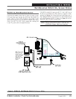
Page 23: ...The OE256 05 Wall Mounted E BUS CO2 Sensor is used to monitor CO2 levels in the space served by the HVAC unit The E BUS CO2 Sensor connects to the VCB X Controller with an EBC E BUS cable It can be da...

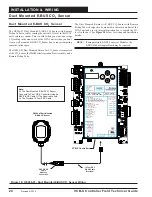
Page 24: ...E256 07 Duct Mounted E BUS CO Sensor 2 Note 1 The Duct Mounted E BUS CO Sensor Connects To The Controller Using An EBC E BUS Cable Of The Required Length Or The Provided 10 Foot EBC Cable 2 VCB X VCB...

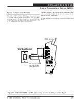
Page 25: ...unit applications controlling one zone The Space Temperature Sensor is a 10K Type III thermistor sensor and should be mounted approximately 5 feet above the floor in the space that is to be controlled...

Page 26: ...r Duct OE231 Supply Air Temperature Sensor AI2 GND VCB X Controller Supply Air Temperature Sensor The OE231 SupplyAir Temperature Sensor must be wired as shown for proper operation The Supply Air Temp...

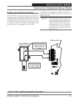
Page 27: ...ted in the upright position as shown in an area that is protected from the elements and direct sunlight Be sure to make the wiring splices inside of the Outdoor Air Temperature Sensor weather tight en...

Page 28: ...OutdoorAir Temperature HumiditySensorinanareathatisnotexposed to direct sunlight The shaded area under the HVAC unit rain hood is normally a good location Unused conduit opening s must have closure p...

Page 29: ...ht The shaded area under the HVAC unit rain hood is normally a good location Unused conduit opening s must have closure plugs installed and must be coated with sealing compound to provide a rain tight...

Page 30: ...required for any VCB X application with DX Cooling that requires Dehumidification The Suction Pressure Transducer is used to measure suction pressure at the HVAC unit s DX evaporator coil suction lin...

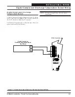
Page 31: ...be wired as shown in Figure 17 below for proper operation of the VCB X Controller s Digital Scroll Compressor The Discharge Temperature Input is a thermistor input There is no polarity requirement for...

Page 32: ...digital compressor to achieve setpoint Figure 18 Digital Compressor Unloader Wiring The Unloader Solenoid output is a triac output The maximum continuous solenoid load is 0 5A and the peak inrush curr...

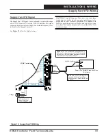
Page 33: ...e VFD Using 18 GA Minimum 2 Conducter Twisted Pair With Shield Cable Wire Shield To GND As Shown AOUT1 GND Shield Figure 19 Supply Fan VFD Wiring Supply Fan VFD Signal The Supply Fan VFD Signal is a u...

Page 34: ...US EXPANSION 24 VAC INPUT VCB X Controller Economizer Damper Actuator The Economizer Damper Actuator signal voltage output using AOUT2 is user adjustable but must be set to 2 10 VDC for this applicati...

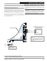
Page 35: ...oller Modulating Heating Device The Modulating Heating Device signal voltage output is a user adjustable signal with a range of 0 10 VDC from AOUT3 when programming the controller The output signal ca...

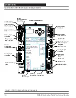
Page 36: ...UILDING PRESSURE SENSING LOCATIONS SIG 2 GND 5V HEAD PRESSURE TRANSDUCER 1 BK RD WH OE231 RETURN AIR TEMP SENSOR LEAVING WATER TEMP SENSOR MOUNT IN LEAVING WATER PIPE MOUNT IN HVAC UNIT RETURN AIR STR...

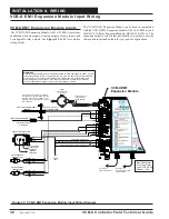
Page 37: ...Y1 3 COM 1 BUILDING PRESSURE DAMPER ACTUATOR 2 Y1 3 COM 1 CONDENSER FAN ECM MOTOR VCB X EM1 Expansion Module WARNING Observe Polarity All boards must be wired with GND to GND and 24VAC to 24VAC Failur...

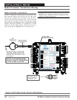
Page 38: ...s installed on a Constant Volume unit it will not affect operation but rather will be used as a status only reading See Figure 24 below for detailed wiring CAUTION It is strongly recommended that you...

Page 39: ...ensor is a 10K Type III thermistor sensor The Return Air Temperature Sensor should be mounted in the return air duct If the system has a Zoning Bypass Damper installed be sure the return air sensor is...

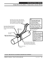
Page 40: ...G WATER E TEMPERATURE SENSOR WITH 91 IMMERSION WELL MOUNT IN LEAVING WATER PIPE OE2 GND STRAP ON O 233 LEAVING E WATER TEMPERATURE SENSOR MOUNT IN LEAVING WATER PIPE To T2 To GND 2 1 Leaving Water Tem...

Page 41: ...ed Wiring Diagram Below Notes 1 Sensor Should Be Mounted At Location Along Pipe Length That Best Represents Desired Temperature Reading 3 All Wiring To Be In Accordance With Local And National Electri...

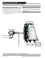
Page 42: ...labeled COM Connect the remaining terminal labeled OUT to SIG1 on the VCB X EM1 terminal block WARNING It is very important to be certain that all wiring is correct as shown in the wiring diagram bel...

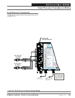
Page 43: ...nect To Expansion Module s When Used Connect To Controller VCB X Size Transformer For Correct Total Load VCB X E 1 Module 5 VA M 5V SIG2 GND 5V HEAD PRESSURE 1 TRANSDUCER BY OTHERS BK RD WH GND T3 GND...

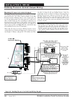
Page 44: ...ding Static Pressure Sensor must be connected in order for the Building Pressure Output to operate correctly CAUTION Variable Frequency Drive units can cause large transient noise spikes that can caus...

Page 45: ...e to maintain the Cooling Supply Air Temperature Setpoint The output is configured for either 0 10 VDC or 2 10 VDC operation and can be configured for direct acting or reverse acting operation See Fig...

Page 46: ...ed for an Air Cooled Condenser default or for a Water Cooled Condenser See Figure 32 for wiring VCB X EM1 Expansion Module AOUT4 24VAC GND Line Voltage Size Transformer For Correct Total Load VCB X E...

Page 47: ...BLOCK AAON V35130 RETURN AIR BYPASS DAMPER RETURN AIR DAMPER ECONO FEEDBACK RST SIG REMOTE FORCED COOLING REMOTE FORCED HEATING REMOTE FORCED DEHUMID GND GND www aaon com www orioncontrols com ANALOG...

Page 48: ...LARITY MUST BE OBSERVED OR THE CONTROLLER WILL BE DAMAGED POWER INPUT TERMINAL BLOCK AAON V35130 RETURN AIR BYPASS DAMPER RETURN AIR DAMPER ECONO FEEDBACK RST SIG REMOTE FORCED COOLING REMOTE FORCED H...

Page 49: ...ertain that all wiring is correct as shown in the wiring diagram below Failure to observe the correct polarity could result in damage to the Damper Actuator or the VCB X Expansion Module RETURN AIR DA...

Page 50: ...le Relay Output 8 EBC E BUS Cable Connect To VCB X Controller EBC E BUS Cable Connect To Next Expansion Board When Used 24 VAC GND 15 VA Minimum Power Required WARNING Observe Polarity All boards must...

Page 51: ...low Measurement Digital Transmitters can be attached to each Adapter Board NOTE If using multiple E BUS Sensors or Modules the E BUS Hub HZ EBC 248 or MS000248 may be required NOTE When configuring th...

Page 52: ...re Reset Signal If the communication is interrupted between the MHGRV X Controller and the VCB X Controller the MHGRV X controller will revert to stand alone operation For more information refer to th...

Page 53: ...tpoint The offset for the Supply Air Temperature Sensor High Limit Temperature Setpoint If the communication is interrupted between the MODGAS X Controller and the VCB X Controller the MODGAS X contro...

Page 54: ...and touch adjacent terminals Confirm that all sensors required for your system are mounted in the appropriate location and wired into the correct terminals on the VCB X Controller After all the above...

Page 55: ...rface Any of these devices or a combination of them can be used to access the status configuration and setpoints of any controller on your communications loop If using the Modular Service Tool or Syst...

Page 56: ...pansion Modules 1 E BUS Digital Room Sensor LCD Display Temp Only or Temp Humidity 2 E BUS Digital Room Sensor No LCD Display Temp Humidity 3 E BUS Space and Return Air CO2 Sensors 4 E BUS connection...

Page 57: ...charge temperature from the Digital Compressor to protect against overheating AI5 Space Temperature Sensor Slide Adjust If the Space Temperature Sensor being used has the optional Slide Adjust feature...

Page 58: ...ured for a Digital Compressor 2 Cooling Stage Configured for each fixed stage of cooling except heat pump compressor 3 Condenser Configured for Condenser Fan or Condenser Water Valve operation This re...

Page 59: ...configure the VCB X Controller for Building Pressure Control Building Pressure Control can be accomplished by using one of two main control methods One control method uses the 0 10 VDC signal to cont...

Page 60: ...urable Relays These relays are configurable by the user For all the available configuration options see Table 5 VCB X EM1 EM2 Expansion Module Inputs Outputs VCB X EM2 Expansion Module AIN1 Economizer...

Page 61: ...of 100 or high percentage Outdoor Air units by tempering the air during the Space Vent Mode of opera tion to prevent dumping of hot or cold air into the space HVAC Mode Set by Remote Contact Input Pro...

Page 62: ...the Active Supply Air Cooling Setpoint One Digital Compressor can be controlled with the VCB X Controller If additional cooling is required fixed compressor stages can be staged on while the Digital C...

Page 63: ...on Mode or a Vent Dehumidification Mode In All Modes while Occupied and Unoccupied Dehumid ification can be initiated anytime in the Occupied or Unoccupied Mode during Cooling Heating Vent or Off Mode...

Page 64: ...WattMaster Controls Inc assumes no liability for any Simultaneous Heating and Cooling application if a SPA is not obtained from the AAON Factory at the time the HVAC unit is ordered When Heating is u...

Page 65: ...lating Heating Proportional Window The larger the Modulating Heating Proportional Window the smaller the signal adjustment will be per Time Period The Time Period is the delay between another increase...

Page 66: ...proportionally reset higher as the CO2 rises within the range set by the Minimum CO2 Level Setpoint and the Maximum CO2 Level Setpoint If the CO2 level reaches the High CO2 Level Setpoint the Economi...

Page 67: ...described above depending on if the Space Temperature is calling for Cooling Heating or Vent Mode of operation Whenever the unit is in CO2 override operation of the Outdoor Air Damper the minimum VFD...

Page 68: ...ill be controlling to a Duct Static Pressure Setpoint The Static Pressure Control Output Signal can be used to control a Supply Fan VFD Direct Acting Operation or a Zoning Bypass Damper Actuator Rever...

Page 69: ...ion is configured the VCB X will use the user adjustable Economizer Outdoor Air Damper output signal AOUT2 Economizer Control Signal to maintain the Building Pressure Setpoint Whenever the Building Pr...

Page 70: ...ling or heating operation and stage it as necessary to maintain the Vent Mode Supply Air Setpoint Preset to halfway between the Mode Enable Setpoints CAV MUA and Condenser Fan Water Valve Operation Du...

Page 71: ...igured as a Heat Pump Compressor rather than a Cooling Stage Heat Pump Operation Heat Pump Standard Defrost Operation If using the VCB X Controller with an installed Defrost Coil Temperature Switch a...

Page 72: ...pressor will be locked at 100 until the Supply Air Temperature SAT rises above the SAT Heating Setpoint plus the Heat Staging Window At that point the Auxiliary Heat will stage off after a stage down...

Page 73: ...d out An alarm LED will indicate Compressor Lockout Power will need to be cycled or a change of Mode i e Cool to Heat will need to occur for compressors to be enabled again 3 If multiple compressors a...

Page 74: ...Protection is activated when the SupplyAirTemperature SAT rises above the High Cutoff Temperature immediate or drops below the Low Cutoff Temperature for 10 minutes Both cutoff setpoints are user adj...

Page 75: ...e Sensor is not detected or if shorted High Supply Air Temperature Cutoff Low Supply Air Temperature Cutoff High Control Temp Low Control Temp Digital Compressor Cutoff Digital Compressor Lockout High...

Page 76: ...int the controller will generate a Low Control Temp Failure Alarm Both offset setpoints are user adjustable Alarms Digital Compressor Cutoff Alarm If the digital compressor discharge temperature rises...

Page 77: ...atus Labeled as configured Trend Logging VAV Zone Controller Alarms Space Sensor Failure Alarm If the controller detects an open or short on the Space Sensor input this alarm will be generated CFM Sen...

Page 78: ...ht up and blink continuously to indicate the VCB X Controller is communicating BACNET This yellow LED will light up and blink continuously to indicate BACnet communications Compressor LEDs ALERT This...

Page 79: ...SHUTDOWN PROOF OF FLOW DIRTY FILTER COIL TEMP SWITCH FAN VFD ECONOMIZER MOD HEATING DIGITAL COMP UNLOADER 24 VAC UNLOAD TERMINALS BINARY INPUTS G OUTPUTS TRIAC OUTPUT ANALO WattMaster Label SW000061...

Page 80: ...be defective Once the controller is done blinking the address the LEDs will blink a code every 10 seconds to indicate controller status If all of these tests are made and the controller still doesn t...

Page 81: ...uge 2 conductor twisted pair with shield wire Belden 82760 or equivalent This allows for all controllers that are connected on the communications loop to be programmed and monitored from one or more o...

Page 82: ...ical Guide 82 Operator Interfaces Modular Service Tool SD System Manager Touch Screen II Personal Computer CommLink and Prism 2 Software Modular System Manager SD Figure 44 Typical Stand Alone System...

Page 83: ...e APPENDIX A 83 Personal Computer CommLink and Prism 2 Software System Manager Touch Screen II Modular Service Tool SD Modular System Manager SD Interconnected System Layout Figure 45 Typical Intercon...

Page 84: ...Zone Zone APPENDIX A VCB X Controller Field Technical Guide 84 Operator Interface Operator Interfaces Figure 46 Typical Networked System Layout Networked System Layout Revised 9 24 13...

Page 85: ...Temperature Resistance Voltage for Type III 10 K Ohm Thermistor Sensors Temp F Temp C Resistance Ohms Voltage Input VDC 10 23 33 93333 4 51 5 20 55 80531 4 45 0 17 77 69822 4 37 5 15 60552 4 29 10 12...

Page 86: ...nce to confirm that the sensor is operating correctly per the table Please follow the notes and instructions the appear after the chart when checking sensors Discharge Thermistor Temperature Resistanc...

Page 87: ...0 25 2 60 2 33 0 10 0 33 2 70 2 41 0 20 0 41 2 80 2 49 0 30 0 49 2 90 2 57 0 40 0 57 3 00 2 65 0 50 0 65 3 10 2 73 0 60 0 73 3 20 2 81 0 70 0 81 3 30 2 89 0 80 0 89 3 40 2 97 0 90 0 97 3 50 3 05 1 00...

Page 88: ...minals PR OUT and GND terminals and compare it to the appropriate chart depending on the refrigerant you are using If the temperature voltage or pressure voltage readings do not align closely with the...

Page 89: ...er measurements reference Table 13 below Head Pressure Transducer Chart Voltage Pressure Voltage Pressure 0 5 0 2 6 350 0 6 17 2 7 367 0 7 33 2 8 384 0 8 50 2 9 400 0 9 67 3 0 417 1 0 83 3 1 434 1 1 1...

Page 90: ...criptions Navigation Keys Figure 47 LCD Display and Navigation Keys Table 14 Navigation Key Functions NAVIGATION KEY KEY FUNCTION MENU Use the MENU key to move through screens within Main Menu categor...

Page 91: ...ess to scroll through the Settings Screens Press to go to the Status Screens Press to go to the Settings Screens Revised 4 24 13 Settings Screens Refer to the following map when navigating through the...

Page 92: ...of operation of the VCB X Controller The mode options are LINE 1 UNOCCUPY Unoccupied OCCUPIED OVERRIDE HOL UNOC Holiday Unoccupied HOL OCC Holiday Occupied FRC OCC Force Occupied FRC UNOC Force Unoccu...

Page 93: ...5 MODGAS ALARM See Missing Expansion Module Alarm MODGAS Board Missing page 75 RLY EXP ALARM See Missing Expansion Module Alarm page 75 Alarm Screens COOLING FAILURE See Mechanical Cooling Failure Ala...

Page 94: ...crease and decrease the value Default is 1 0 AUTO Econo 1 0 0 0 10 0 vdc ECONOMIZER VFD 0 0 to 10 0 Active Force Mode Press the UP and DOWN buttons to increase and decrease the value Default is 1 0 AU...

Page 95: ...SHLD 24 VAC POWER ONLY WARNING POLARITY MUST BE OBSERVED OR THE CONTROLLER WILL BE DAMAGED www aaon com www orioncontrols com VCB X CONTROLLER Orion No OE335 26B VCBX AAON V28940 AAON Coil J00142 ANAL...

Page 96: ...ssure Sensor Suction Pressure AI 19 Current Suction Pressure Value Head Pressure 1 AI 20 Current Value of the Head Pressure 1 Reading CO2 AI 21 Current Indoor CO2 Level BACnet Properties for the VCB X...

Page 97: ...ing Setpoint AV 4 This is the Heating Mode Enable Setpoint used only in Hood On Mode 1 110 BACnet Properties for the VCB X Controller Parameter Object Description Limits Unoccupied Cooling Offset AV 5...

Page 98: ...if the outdoor drybulb dewpoint or wetbulb temperature falls below this setpoint 30 80 BACnet Properties for the VCB X Controller Parameter Object Description Limits Heat Wheel Defrost Enable Setpoint...

Page 99: ...Main Fan VFD in Cooling Mode AV 40 In Single Zone VAV config uration this is the fan speed at which the VFD will start when Cooling is initiated In a VAV configuration this is the lowest fan speed all...

Page 100: ...de 240 PSI 420 PSI Minimum Outdoor Air CFM AV 59 Minimum Outdoor Airflow CFM Setpoint 10K 200K BACnet Properties for the VCB X Controller Parameter Object Description Limits Outdoor Air CFM Proportion...

Page 101: ...ured but not detected Bad or Missing MODGAS Board BI 19 The MODGAS board is configured but not detected BACnet Properties for the VCB X Controller Parameter Object Description Limits Bad or Missing 12...

Page 102: ...n Board On Board Relay 2 BI 38 Current status of Relay 2 on VCB X Main Board On Board Relay 3 BI 39 Current status of Relay 3 on VCB X Main Board BACnet Properties for the VCB X Controller Parameter O...

Page 103: ...us of the Fan Relay on the MODGAS X Controller MODGAS X Controller Low Speed Relay BI 65 Current Status of the Low Speed Relay on the MODGAS X Controller MODGAS X Controller AUX 1 Relay BI 66 Current...

Page 104: ...Failure 15 Mechanical Heating Failure 16 Fan Proving Alarm 17 Dirty Filter Alarm 18 Emergency Shutdown Alarm 19 High Supply Air Temp Cutoff 20 Low Supply Air Temp Cutoff 21 High Control Mode Signal Al...

Page 105: ...E335 26B VCBX 2 13 BACnet Standardized Device Profile Annex L BACnet Application Specific Controller B ASC BIBBs Supported Data Sharing ReadProperty B DS RP B ReadPropertyMultiple B DS RPM B WriteProp...

Page 106: ...larms 76 High and Low Control Temp Failure 76 High and Low Supply Temp Alarm 76 High Space Temp Alarm 77 A B Mechanical Cooling Failure 75 Mechanical Heating Failure 75 Outdoor Air Temperature Sensor...

Page 107: ...Dehumidification 64 Return Air Bypass Damper Control 64 Dehumidification Priority 6 Diagnostic LEDs 78 79 80 Diagrams Building Pressure Control Output Wiring 44 Building Static Pressure Sensor Wiring...

Page 108: ...n Module Wiring 50 E BUS Adapter 9 E BUS Adapter Board 12 51 E BUS Adapter Hub 12 E BUS Cables 10 E BUS CO2 Duct Sensor 9 E BUS CO2 Wall Mounted Sensor 9 Described 9 Wiring 23 E BUS Digital Room Senso...

Page 109: ...X EM1 Expansion Module 59 Input Wiring VCB X Controller 20 Instructions Addressing 54 Interconnected System 81 Interconnected System Layout 83 Internal Week Schedule 61 Internet LAN Connection 11 IP...

Page 110: ...oor Air Temperature Sensor 27 OE256 05 9 Wiring 23 OE256 05 Wall Mounted E BUS CO2 Sensor 23 OE256 07 9 24 Wiring 24 OE256 07 E BUS CO2 Sensor 24 OE258 01 Building Static Pressure Sensor 10 42 44 OE25...

Page 111: ...y Alarm Active 58 Relay LEDs 78 Relay Outputs 77 Relays 21 Aux Heat 58 Condenser 58 Cooling Stage 58 Digital Compressor 58 Economizer Active 58 Emergency Heat 58 Heating Stage 58 Heat Pump Compressor...

Page 112: ...ssure Sensor 38 Static Pressure Transducer Wiring 38 STATUS 1 LED 55 78 80 STATUS 2 LED 55 78 80 Steam Valve 5 Strap on Temperature Sensor Kit 10 Suction Pressure Detection 73 Suction Pressure Transdu...

Page 113: ...troller Input Wiring 20 VCB X Controller Output Wiring 21 VCB X EM1 Expansion Module 8 Building Pressure Control Signal 60 Building Static Pressure Sensor Input 59 Condenser Fan VFD Signal 60 Condenso...

Page 114: ...4 Relays 21 Return Air Bypass 49 Return Air Bypass Damper Actuator 49 Return Air Damper Actuator 48 Return Air Temperature Humidity Sensor 29 Return Air Temperature Sensor 29 39 Space Temperature Sens...

Page 115: ...NOTES VCB X Controller Field Technical Guide 115...

Page 116: ...CBX FIELD TGD 01Q Printed in the USA August 2014 All rights reserved Copyright 2014 WattMaster Controls Inc 8500 NW River Park Drive Parkville MO 64152 Phone 866 918 1100 www orioncontrols com Fax 816...

Reviews: