Zone
Zone
INSTALLATION & WIRING
VCB-X Controller Field Technical Guide
42
Building Static Pressure Sensor Wiring
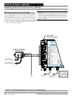
Figure 28: OE258-01 Building Static Pressure Sensor Wiring Diagram
Building Static Pressure Sensor
The OE258-01 Building Static Pressure Sensor must be wired as
shown in
Figure 28
below. There are 3 terminal connections on
the Building Static Pressure Sensor. Connect the power side of the
24 VAC power source to the terminal labeled “+ EXC.” Connect
the GND side of the 24 VAC power source to the terminal labeled
“- COM.” Connect the remaining terminal labeled “OUT” to SIG1
on the VCB-X EM1 terminal block.
WARNING:
It is very important to be certain that all wiring is
correct as shown in the wiring diagram below. Failure to observe
the correct polarity will result in damage to the HVAC Unit
Controller, Building Static Pressure Sensor, and the VCB-X
Expansion Module.
SIG1
GND
VCB-X EM1
Expansion Module
Connect To
Expansion Module(s)
(When Used)
Connect To
Controller
VCB-X
Size Transformer
For Correct Total
Load. VCB-X E 1
Module = 5 VA
M
EXC
COM
OUT
LOW
-
+
+
+
Tubing To Building
Pressure Sensing Location
Tubing To Atmospheric
Pressure Sensing Location
-
+
OE258-01 Building Static
Pressure Sensor
HIGH
To 24
VAC
2
1
Revised 7/30/13


