2 © 2009 Directed Electronics—All rights reserved.
FRONT PANEL
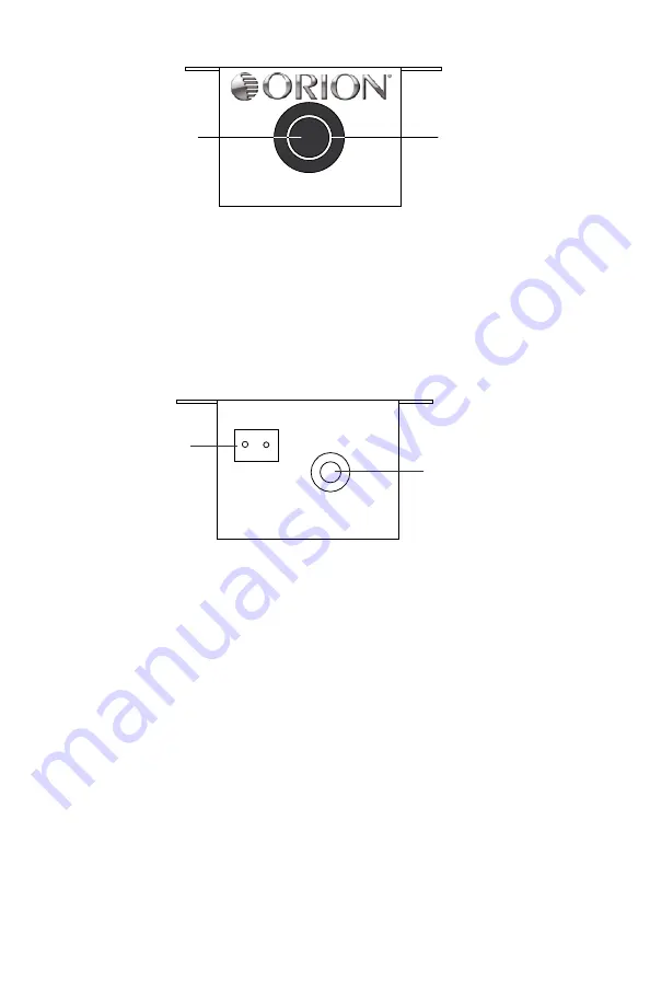
MIN
MAX
(1) ILLUMINATED RING
(2) REMOTE GAIN
CONTROL
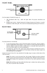
The front panel of the RGC2 consists of:
1. LED illuminated outer ring - which will glow (when the power connections are
made).
2. Remote Gain Control - Rotate clockwise to increase the amount of gain, or counter-
clockwise to reduce the gain. This control can be recessed by pushing on the control.
REAR PANEL
LED
GND +12V
(2) 3.5mm “MINI”
PHONE JACK
(1) TWO-WIRE
LED HARNESS
The rear panel has 2 connections:
A two-wire harness allows control of the illumination of the LED. Connect the Red +
1.
wire to a illumination control output, or to a source of 12-15V power (current draw is
less than 20mA). Connect the Black or GND lead to a convenient power ground. The
control and illumination circuits are independent.
A standard
2.
1/8" (3.5mm) "mini" phone jack connects the gain control knob to the cor-
responding amplifier via a 2 conductor, 15 foot cable. Connect the other connector to
the remote jack on the amplifier.
Attach the body of the unit to the underside of the dash using 2 screws on either side of the
control housing.
Note:
The control can be removed from the housing if flush-mounting is desired.
Remove the two hex head screws at the side. Remove the 2 Phillip’s head screws secur-
ing the PCB. Remove the ring retainer on the front of the control, and then remove
the PCB.
Note:
Before drilling any holes verify that there are no obstructions (wiring, ventila-
tion, etc) on the other side of the dash.


