6
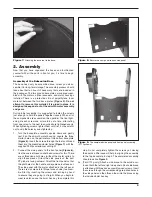
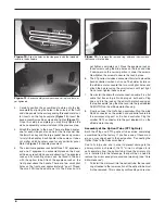
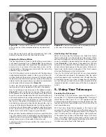
3. Carefully position the assembled structure onto the top
baseplate by aligning the holes in the cutouts of the front
and side panels to the corresponding threaded metal col-
lar inserts on the top baseplate
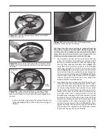
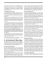
(Figure 10). Insert the
base assembly machine screws and tighten
(Figure 11).
Once this setup is complete you may firmly tighten the
six base assembly screws installed in the previous step.
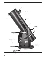
4. Attach the handles to the base. There are three handles,
one for each side panel and one for the front panel. Use
the 6mm hex key and the large socket head cap screws
to install the handles. Each handle is the same so it does
not matter which handle is used for any particular panel.
Refer to
Figure 1 for handle placement.
5. The aluminum eyepiece rack holds three 1.25" eyepieces
and one 2" eyepiece in a convenient place on the base,
within easy reach while you are observing. The eyepiece
rack and its mounting screws can be found in the box
with the optical tube. Attach the eyepiece rack on the
front panel above the handle. There are two small pilot
holes on the front panel approximately 6" apart. Thread
the small Phillips-head screws into the holes but do
not tighten completely yet. Place the eyepiece rack on
those screws using the wide holes on the rack and slide
it downward so the narrow portion is under the screws.
Now tighten the screws to secure the rack in place.
6. The XTg series includes a convenient holster to place the
hand controller in when not in use. The holster installs on
the altitude motor. Locate the two small pilot holes and
attach the holster using the small screws until just tight.
Do not over-tighten these screws!
7. Now install the azimuth motor connection cable. It is a flat
cable that has an 8-pin RJ-45 plug on both ends. Plug
one end into the jack on the azimuth motor housing on
the top baseplate; plug the other end into the jack labeled
AZ MOTOR on the altitude motor housing.
8. Finally, connect the GoTo hand controller. Plug the wide
RJ-45 connector on the coiled hand controller cable into
the corresponding port on the hand controller. Plug the
smaller RJ-12 connector into the port labeled HC on the
altitude motor housing.
assembly of the optical tube (Xt12g only)
Both the XT8g and XT10g optical tubes arrive completely
assembled from the factory. If you have one of these mod-
els, you may skip ahead to the next section, “Connecting the
Optical Tube to the Dobsonian Base”.
Due to its large size, and in order to prevent damage to the
primary mirror in shipment, the 12" mirror is shipped in its
cell separately from the optical tube. Once the primary mir-
ror is installed into the telescope, there will be no need to
remove the mirror except for occasional cleaning (see “Care
& Maintenance”).
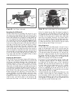
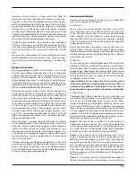
1. To install the mirror cell into the optical tube, the rear end
ring attached to the lower section of the optical tube must
first be removed. This is done by unthreading and remov-
Figure 10.
Align the holes on the side panels with the threaded
inserts in the baseplate.
Figure 11.
Base assembly machine screws set in place, but not
yet tightened.
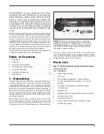
Figure 12.
To remove the rear end ring, unthread the six screws
that connect it to the tube.
Threaded inserts
Cutout holes

