background image

18

appendix B: Periodic Error 

correction (PEc) 

(Requires an illuminated reticle eyepiece capable of producing 
at least 300X magnification when used with your telescope. 
For best results, the true field of view should not exceed 10 
arcminutes.)
Periodic errors are inherent in almost all worm gears due to 
slight eccentricities and misalignments. The PEC (Periodic 
Error Correction) Training function provides a manual correct-
ing method to reduce the amplitude of the worm gear errors. 
By recording a full cycle of guiding actions, the SkyView Pro 
GoTo system can compensate for drifting in the R.A. sidere-
al tracking caused by periodic errors. The description below 
will lead you on a step-by-step procedure for performing the 
PEC. 

Note: The  PEC  training  function  is  recommended  for 
advanced  users  with  interest  in  long-exposure  astro-
photography only. Careful guiding is required. Standard 
sidereal tracking is sufficient for all casual visual applica-
tions of the SkyView Pro GoTo system, and PEC training 
is not required.

PEc training

1.   Perform an accurate polar alignment using the polar axis 

finder scope.

2.   Electronically slew the telescope mounted on the SkyView 

Pro to a star with a small value DEC coordinate (DEC 
b10° and –10°). This object will be used as the 
guide star. 

3.   Activate “Sidereal Tracking”  from  the  Setup  menu  (see 

“Setup Functions”). Once tracking has initiated, press ESC 
to return to the Setup menu. 

4.   Rotate the reticle eyepiece in the focuser (or diagonal) 

until the R.A. movement of the star becomes parallel to 
(matches) one of the illuminated crosshairs 

5.   Move the guide star designated in step 2 to the center of 

the eyepiece field of view using the direction buttons. 

6.   On the hand controller, select PEC Training in the Utility 

Functions and press ENTER.

Note:  Utility  Functions  can  be  accessed  by  pressing  the 
UTILITY quick rererence button on the hand controller.
7.   Select the R.A. guide speed for the PEC Training. You have 

two guide speed choices: 1) 0.25X and 2) 0.5X. Press the 
numeric button 1 to choose a guide speed of 0.25X or 
press 2 to choose a guide speed of 0.5X.  

8.   The SkyView Pro GoTo hand controller will display the 

current time once the guide speed has been selected, 
indicating the recording has begun. 

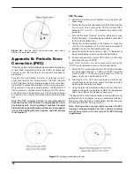
9.   Using the left or right direction button only, move the tele-

scope so the guide star remains centered in the eyepiece 
field of view (Figure 23). Repeat as necessary.

The SkyView Pro GoTo hand controller will record the manual 
guiding actions for 8 minutes in order to characterize the peri-
odic errors. Pressing ESC will immediately stop the recording 
and exit from the PEC Training function. 

Note: Guiding actions are recorded even when the PEC 
training is stopped midway. The PEC + sidereal tracking 
will not be accurate until a full cycle of the PEC Training 
is performed.

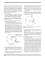
Figure  22. 

Using  the  optical  axis  offset  screws  move  Polaris 

halfway to the eyepiece’s center.

Figure 23. 

Drifting caused by periodic error.

Summary of Contents for SkyView Pro

Page 1: ...v B 02 09 Providing Exceptional Consumer Optical Products Since 1975 Customer Support 800 676 1343 E mail support telescope com Corporate Offices 831 763 7000 89 Hangar Way Watsonville CA 95076 Orion...

Page 2: ...parts on parts list are shown Motor control box bracket R A GoTo motor cover Dec GoTo motor cover Dec GoTo motor Motor control box GoTo hand controller bracket GoTo hand controller Motor cables GoTo h...

Page 3: ...the mount by loosening the Phillips head screw on the bottom of the cover Figure 2 Slide the cover off the mount Congratulations on your purchase of the Orion SkyView Pro GoTo system The GoTo system...

Page 4: ...eeth of the brass gear Figure 6 Also make certain the gears are not too tightly pressed together You may have to adjust the way the gears mesh by tightening or loosening the socket head cap screw that...

Page 5: ...otor assembly is identified by its black rectangular body Figure 9 It is attached to the equato rial mount using the Dec GoTo motor attachment screw that goes through the hole in the flange at the top...

Page 6: ...e two 8 pin circular jacks 2 Slide the motor control box into the motor control box bracket 3 Connect one end of the 13 long motor cable to the 8 pin circular jack marked R A IN on the R A GoTo motor...

Page 7: ...d Controller s Firmware Functions of the GoTo Hand Controller There are four main categories of control buttons on the GoTo hand controller Figure 15a 1 Mode buttons 2 Directional buttons 3 Scroll but...

Page 8: ...levers engaged 3 Turn on the power switch on the motor control box 4 The initial screen displayed on the hand controller is the version screen Press ENTER to proceed 5 The hand controller s LCD scree...

Page 9: ...st of stars that can be used as the second alignment star Choose a star using the scroll buttons and press ENTER to confirm your choice Repeat the centering procedure for the second alignment star usi...

Page 10: ...LCD will ask View Object Press ENTER to issue a command to the mount to GoTo the star If the mount is under the control of a computer running planetarium software click on the star to slew the mount...

Page 11: ...features of the system Utility Functions Utility Functions are useful tools that provide simple yet handy processes to enhance your observing experience Show Position Displays the coordinates right a...

Page 12: ...tton You can also select User Defined in the Object Catalog menu and then press ENTER 2 Choose Recall Object and press ENTER 3 Select the User Object number representing the object you wish to view us...

Page 13: ...s DC power jack The hand controller will beep and display SynScan Update Ver x x on the LCD screen 3 Run the Firmware Loader program on your computer 4 Click on the Browse box and select the OrionVxx...

Page 14: ...14 SkyView Pro GoTo Hand Controller Menu Tree...

Page 15: ...ence by one or more of the following measures Reorient or relocate the receiving antenna Increase the separation between the equipment and receiver Connect the equipment into an output on a circuit di...

Page 16: ...until the counterweight shaft is parallel to the ground as shown in Figure 19a 7 Using the Dec direction button on the hand controller adjust the telescope in Dec so Polaris lies on the R A crosshairs...

Page 17: ...n the mounting plate Figure 20 gently push the telescope horizontally to determine direction of optical axis offset Figure 19a b Rotate the telescope 180 about the R A axis Figure 21a Adjust the optic...

Page 18: ...ted press ESC to return to the Setup menu 4 Rotate the reticle eyepiece in the focuser or diagonal until the R A movement of the star becomes parallel to matches one of the illuminated crosshairs 5 Mo...

Page 19: ...232 mode in order to establish an interface connection with a PC Under the UTILITIES menu select RS232 and press ENTER to initiate the computer interface mode The hand controller will now communicate...

Page 20: ...that proves to be defective provided it is returned postage paid to Orion Warranty Repair 89 Hangar Way Watsonville CA 95076 If the product is not registered proof of purchase such as a copy of the or...

Reviews: