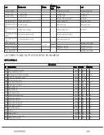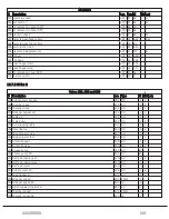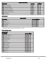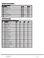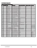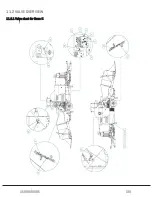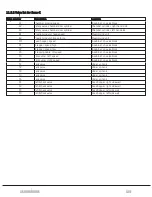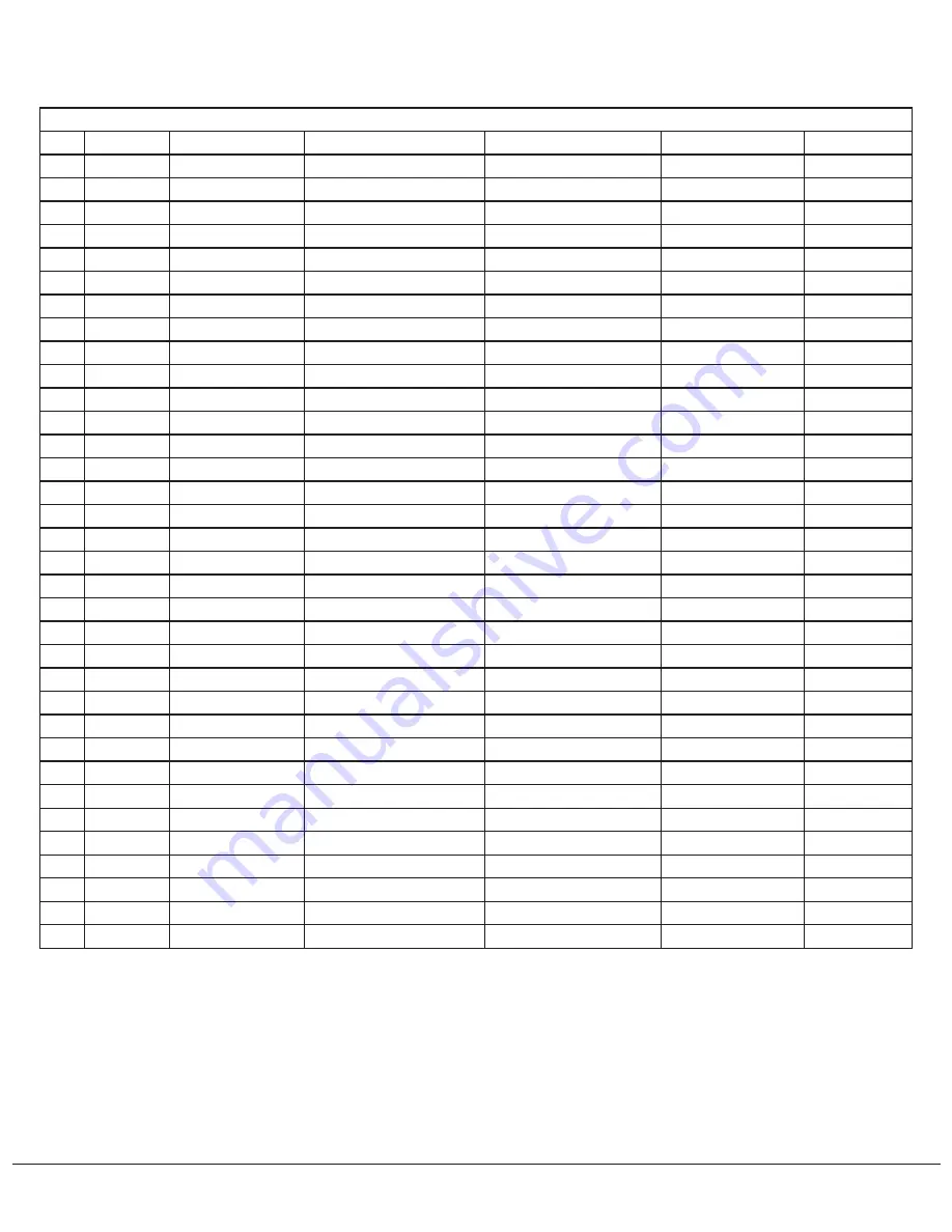
11.1.5 Hydraulic diagram list
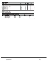
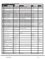
Outputs on controllers for standard system
No.
Description Type
Brand & type
Current drawn @ 24Vdc
Resistance in Ohms Comment
V1
Digital valve
Comatrol SV-15-34-04
1,38 A
17
V2
Digital valve
Comatrol SV-15-34-05
1,38 A
17
V3
Digital valve
Comatrol SV-15-34-05
1,38 A
17
V4
Digital valve
Comatrol SV-15-34-04
1,38 A
17
V5
Digital valve
Comatrol SV-15-34-05
1,1 A
22
V6
Digital valve
Comatrol SV-15-34-05
1,1 A
22
V7
Digital
Comatrol EVK 06/C5
1,1 A
22
V8
Digital valve
Comatrol SV-15-34-02
1,38 A
17
V9
Digital valve
Comatrol SV-15-34-04
1,38 A
17
V10
Digital valve
Comatrol EVK 06/C5
1,1 A
22
V11
Digital valve
Comatrol SV-15-34-05
1,1 A
22
V12
Digital valve
Comatrol SV-15-34-05
1,1 A
22
V13
Electric motor
Bekamax EP-1
1,1 A at full load, 3A fuse
V17
Digital valve
Comatrol SV-15-34-05
1,38 A
17
V18
Digital valve
Comatrol SV-15-34-05
1,38 A
17
V19
Digital valve
Comatrol SV-15-34-02
1,38 A
17
V24
Digital valve
Comatrol SV-15-34-04
1,38 A
17
V25
Digital valve
Comatrol SV-15-34-04
1,38 A
17
V30
Proportional valve Comatrol PSV10-NC
0,9 A (200 mA min)
16
V31
Buzzer
Fulleon ROLP/SV/W/S
32 mA
V32
Servo solenoid
Samhydraulik SH6V
0,68 A (230 mA min)
24,6
V33
Relay
Bosch 0 332 209 206 896
0,1 A
215
Sinking output
V34
Relay
Bosch 0 332 209 206 896
0,1 A
215
Sinking output
V35
Digital valvevalve
Camozzi U77
0,15 A
160
Sinking output
V36
Proportional valve Comatrol PSV1-NC
0,9 A (250 mA min)
17
V37
Proportional valve Comatrol PSV1-NC
0,9 A (250 mA min)
17
V39
Digital valve
Comatrol SVP10-NOR
1,1 A
22
V40
Digital valve
Comatrol SVP10-NOR
1,1 A
22
V51
Digital valve
Comatrol SV-15-34-03
1,38 A
17
F25 only
V52
Digital valve
Comatrol SV-15-34-03
1,38 A
17
F25 only
V53
Digital valve
Comatrol SV-15-34-01
1,1 A
22
F25 only
V54
Digital valve
Comatrol SVP08-NCR
1,38 A
17
F25 only
V55
Digital valve
Comatrol SVP08-NCR
1,38 A
17
F25 only
V56
Digital valve
Comatrol EVK 06/C5
1,1 A
22
F25 only
11 HYDRAULICS
132
Summary of Contents for Dens-X Compactor
Page 14: ...1 6 DECLARATION OF CONFORMITY 1 GENERAL 14...
Page 103: ...8 7 MANUAL LUBRICATION CHARTS 8 7 1 The compactor 8 LUBRICATION 103...
Page 104: ...8 7 2 Feed hopper F25 8 LUBRICATION 104...
Page 105: ...8 7 3 Flexible drawbar 8 LUBRICATION 105...
Page 109: ...10 1 MAIN POWER SUPPLY E STOP SWITCHES AND ELECTRICAL CABINET 10 ELECTRICS 109...
Page 110: ...10 2 ELECTRICAL CABINET POWER SUPPLY RAIL 10 ELECTRICS 110...
Page 111: ...10 3 SENSORS AND MANUAL CONTROLS 10 ELECTRICS 111...
Page 112: ...10 4 VALVES FAN MOTORS AND PUMPS 10 ELECTRICS 112...
Page 124: ...10 9 SENSOR OVERVIEW 10 ELECTRICS 124...
Page 128: ...11 1 1 Complete diagram 11 HYDRAULICS 128...
Page 129: ...11 1 2 Wrapping table chamber and elevator control 11 HYDRAULICS 129...
Page 130: ...11 1 3 Plastic tying unit sub conveyor and feed hopper 11 HYDRAULICS 130...
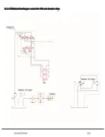
Page 131: ...11 1 4 Additional feed hopper control for F25 and chamber drive 11 HYDRAULICS 131...
Page 133: ...11 2 VALVE OVERVIEW 11 2 1 Valve chart for Dens X 11 HYDRAULICS 133...
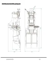
Page 137: ...12 6 3 Dimensional sketch F25 operating mode 12 SPECIFICATIONS 137...
Page 138: ...12 6 4 Dimensional sketch F25 transport mode 12 SPECIFICATIONS 138...
Page 142: ...M Maintenance 13 69 71 INDEX 142...

