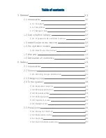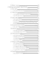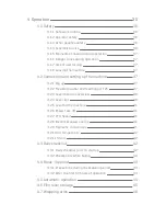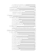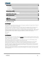
2 Safety
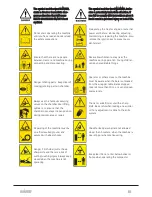
2.2.1 Warning, danger and caution
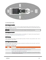
2.5.4 Environmental protection
2.1 INTRODUCTION
This operator’s safety manual is made to describe safe and good routines when operating the compactor.
On the other hand, it is not possible to describe every operational and safety matters that may arise. Care-
fully consider all your actions, if it is posing a safety hazard to you, or others close to the compactor! • Acci-
dents may kill you or make you disabled. • Accidents can be avoided.
2.2 SYMBOLS
This symbol means:
l
ATTENTION!
l
BE CAUTIOUS!
l
CONSERN FOR YOUR PERSONAL SAFETY!
When you see this symbol in the operator’s manual, be aware that violation of instructions given, can
cause you or others in the working area of the machine, being injured or killed.
2.2.1 Warning, danger and caution
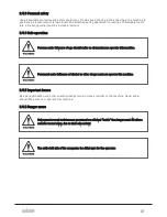
Each time you see the words and symbols as shown below, please note the different directions they sym-
bolize. The pictograms are used in this manual or/and on the machine.
2 SAFETY
15
Summary of Contents for Dens-X Compactor
Page 14: ...1 6 DECLARATION OF CONFORMITY 1 GENERAL 14...
Page 103: ...8 7 MANUAL LUBRICATION CHARTS 8 7 1 The compactor 8 LUBRICATION 103...
Page 104: ...8 7 2 Feed hopper F25 8 LUBRICATION 104...
Page 105: ...8 7 3 Flexible drawbar 8 LUBRICATION 105...
Page 109: ...10 1 MAIN POWER SUPPLY E STOP SWITCHES AND ELECTRICAL CABINET 10 ELECTRICS 109...
Page 110: ...10 2 ELECTRICAL CABINET POWER SUPPLY RAIL 10 ELECTRICS 110...
Page 111: ...10 3 SENSORS AND MANUAL CONTROLS 10 ELECTRICS 111...
Page 112: ...10 4 VALVES FAN MOTORS AND PUMPS 10 ELECTRICS 112...
Page 124: ...10 9 SENSOR OVERVIEW 10 ELECTRICS 124...
Page 128: ...11 1 1 Complete diagram 11 HYDRAULICS 128...
Page 129: ...11 1 2 Wrapping table chamber and elevator control 11 HYDRAULICS 129...
Page 130: ...11 1 3 Plastic tying unit sub conveyor and feed hopper 11 HYDRAULICS 130...
Page 131: ...11 1 4 Additional feed hopper control for F25 and chamber drive 11 HYDRAULICS 131...
Page 133: ...11 2 VALVE OVERVIEW 11 2 1 Valve chart for Dens X 11 HYDRAULICS 133...
Page 137: ...12 6 3 Dimensional sketch F25 operating mode 12 SPECIFICATIONS 137...
Page 138: ...12 6 4 Dimensional sketch F25 transport mode 12 SPECIFICATIONS 138...
Page 142: ...M Maintenance 13 69 71 INDEX 142...


