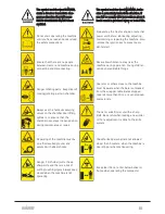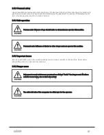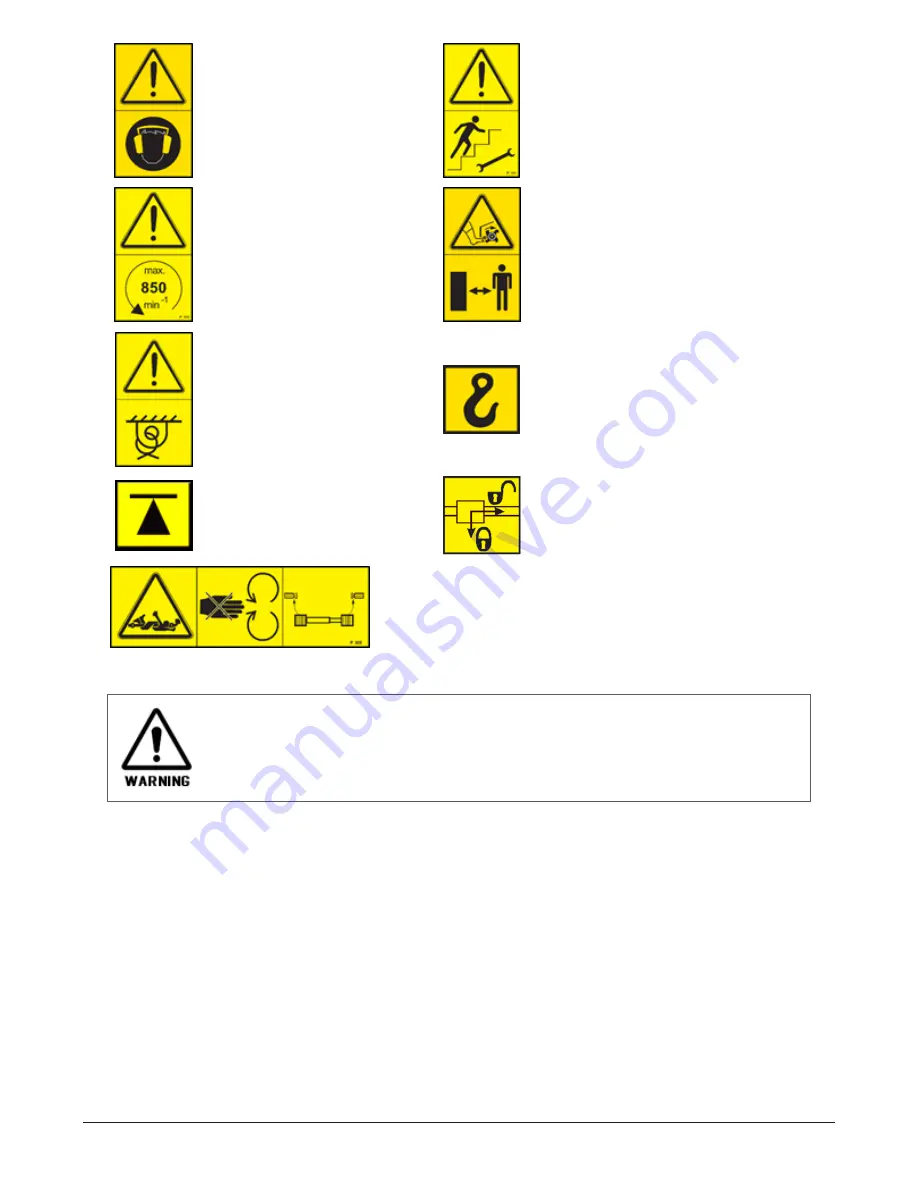
Noise zone. Use ear protection.
Stairway. Access only for operators or
mechanics.
Make sure the transmission is run-
ning with the correct speed and
direction. Wrong speed and/or
direction can damage machinery and
may cause great danger to persons
nearby. The machine is designed for
a PTO-speed of 850 rpm.
Stay clear, rotating machinery.
Strapping point.
Lifting point.
Jacking point.
Hydraulics securing valves, locking the tail-
gate lifting cylinders.
Between the tractor and the machine, there is a rotating PTO-
shaft. No one is allowed to stand between the tractor and the
machine while the engine is running. Do not wear loose clothes,
scarfs etc.
Warning signs, indicating danger or warning attached to the machine, must not be removed or
painted over. Unreadable signs shall be replaced by new ones. These can be ordered from Orkel
AS.
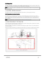
2.3 EMERGENCY STOP
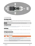
The machine is equipped with 5 manual emergency stop buttons. Four are accessible from ground level
and one on top of the machine as indicated on
.
2 SAFETY
17
Summary of Contents for Dens-X Compactor
Page 14: ...1 6 DECLARATION OF CONFORMITY 1 GENERAL 14...
Page 103: ...8 7 MANUAL LUBRICATION CHARTS 8 7 1 The compactor 8 LUBRICATION 103...
Page 104: ...8 7 2 Feed hopper F25 8 LUBRICATION 104...
Page 105: ...8 7 3 Flexible drawbar 8 LUBRICATION 105...
Page 109: ...10 1 MAIN POWER SUPPLY E STOP SWITCHES AND ELECTRICAL CABINET 10 ELECTRICS 109...
Page 110: ...10 2 ELECTRICAL CABINET POWER SUPPLY RAIL 10 ELECTRICS 110...
Page 111: ...10 3 SENSORS AND MANUAL CONTROLS 10 ELECTRICS 111...
Page 112: ...10 4 VALVES FAN MOTORS AND PUMPS 10 ELECTRICS 112...
Page 124: ...10 9 SENSOR OVERVIEW 10 ELECTRICS 124...
Page 128: ...11 1 1 Complete diagram 11 HYDRAULICS 128...
Page 129: ...11 1 2 Wrapping table chamber and elevator control 11 HYDRAULICS 129...
Page 130: ...11 1 3 Plastic tying unit sub conveyor and feed hopper 11 HYDRAULICS 130...
Page 131: ...11 1 4 Additional feed hopper control for F25 and chamber drive 11 HYDRAULICS 131...
Page 133: ...11 2 VALVE OVERVIEW 11 2 1 Valve chart for Dens X 11 HYDRAULICS 133...
Page 137: ...12 6 3 Dimensional sketch F25 operating mode 12 SPECIFICATIONS 137...
Page 138: ...12 6 4 Dimensional sketch F25 transport mode 12 SPECIFICATIONS 138...
Page 142: ...M Maintenance 13 69 71 INDEX 142...

