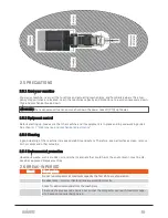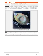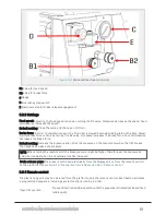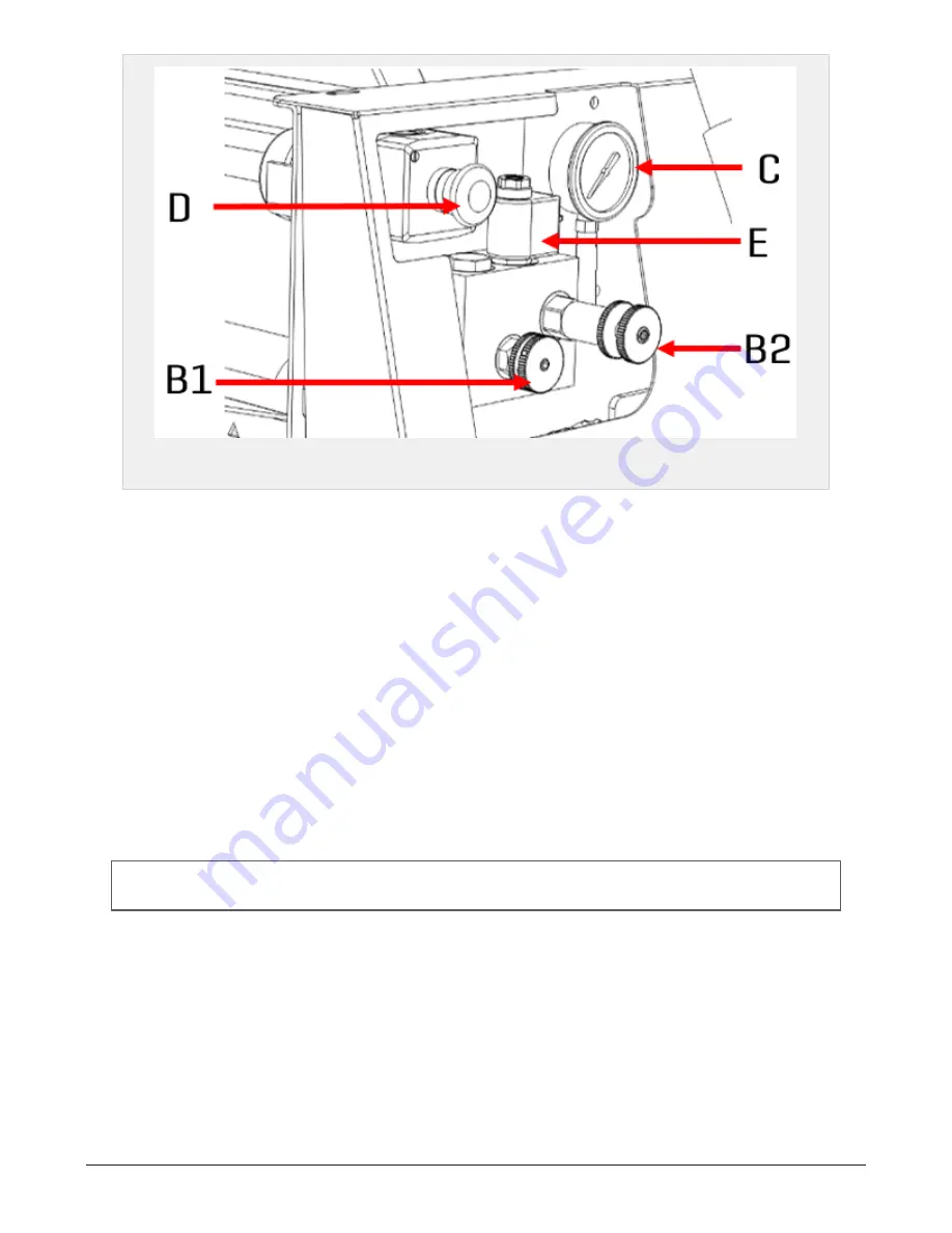
Figure 3.4 :
Brake and feed speed controls
B1 Valve for feed speed
B2 Valve for brake force
C Gauge
D Emergency stop switch
E Electrical valve for brake release/engagement
3.6.3 Settings
Feed speed: Adjusting the feed speed is done by turning the B1 valve. Clockwise decreases the speed. Coun-
terclockwise increases the speed.
Default setting: Close the valve and then open 3/4 turn.
Brake force: In order to maintain tension, the film roller is slowed down when being laid on the bale. Adjust-
ing this brake force is done by turning the B2 valve. Clockwise increases the brake force. Counterclockwise
decreases the brake force.
Default setting: Increase the pressure and notice the pressure on the manometer when the film breaks.
Then slightly decrease the pressure.
NOTE: When starting the machine cold, the brake pressure might be higher. Therefore, set the pressure by
cold oil or readjust when the oil temperature has increased.
Brake release valve: The brake is controlled electrically from the display unit or from the remote control
on the platform. See
section 6.1.6 "Manual controls"
and
section 3.6.4 "Remote control"
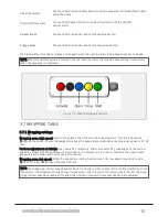
3.6.4 Remote control
The plastic tying unit may be operated from the platform using the remote control. Each button activates
a programmed sequence, including several functions running in order:
Open film system:
Press and hold red and blue buttons until the sequence is finished (knife and feed
rollers open).
3 SETTINGS AND HYDRAULIC ADJUSTMENTS
29
Summary of Contents for Dens-X Compactor
Page 14: ...1 6 DECLARATION OF CONFORMITY 1 GENERAL 14...
Page 103: ...8 7 MANUAL LUBRICATION CHARTS 8 7 1 The compactor 8 LUBRICATION 103...
Page 104: ...8 7 2 Feed hopper F25 8 LUBRICATION 104...
Page 105: ...8 7 3 Flexible drawbar 8 LUBRICATION 105...
Page 109: ...10 1 MAIN POWER SUPPLY E STOP SWITCHES AND ELECTRICAL CABINET 10 ELECTRICS 109...
Page 110: ...10 2 ELECTRICAL CABINET POWER SUPPLY RAIL 10 ELECTRICS 110...
Page 111: ...10 3 SENSORS AND MANUAL CONTROLS 10 ELECTRICS 111...
Page 112: ...10 4 VALVES FAN MOTORS AND PUMPS 10 ELECTRICS 112...
Page 124: ...10 9 SENSOR OVERVIEW 10 ELECTRICS 124...
Page 128: ...11 1 1 Complete diagram 11 HYDRAULICS 128...
Page 129: ...11 1 2 Wrapping table chamber and elevator control 11 HYDRAULICS 129...
Page 130: ...11 1 3 Plastic tying unit sub conveyor and feed hopper 11 HYDRAULICS 130...
Page 131: ...11 1 4 Additional feed hopper control for F25 and chamber drive 11 HYDRAULICS 131...
Page 133: ...11 2 VALVE OVERVIEW 11 2 1 Valve chart for Dens X 11 HYDRAULICS 133...
Page 137: ...12 6 3 Dimensional sketch F25 operating mode 12 SPECIFICATIONS 137...
Page 138: ...12 6 4 Dimensional sketch F25 transport mode 12 SPECIFICATIONS 138...
Page 142: ...M Maintenance 13 69 71 INDEX 142...

