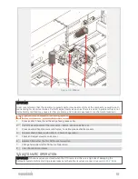
3. Connect the hydraulic hoses to the tractors hydraulic take outs.
4. Connect the PTO drive shaft according to the manufacturers instructions. The PTO drive shaft pro-
tection shall be intact and secured in both ends. Read the safety guidelines enclosed with the PTO
drive shaft.
5. Pull the nylon ropes to disengage the drawbar transport safety lock.
6. Swing the flexible drawbar all the way out to either side (see
section 3.8.1 "Flexible drawbar"
).
7. Engage the main power switch to activate the compactor battery pack (
).
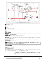
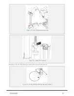
8. Start levelling the machine with the hydraulic jack stands, left- and right rear (lever 1 and 2, see
). Use sight glasses mounted on the frame to verify levelling.
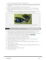
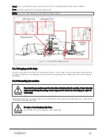
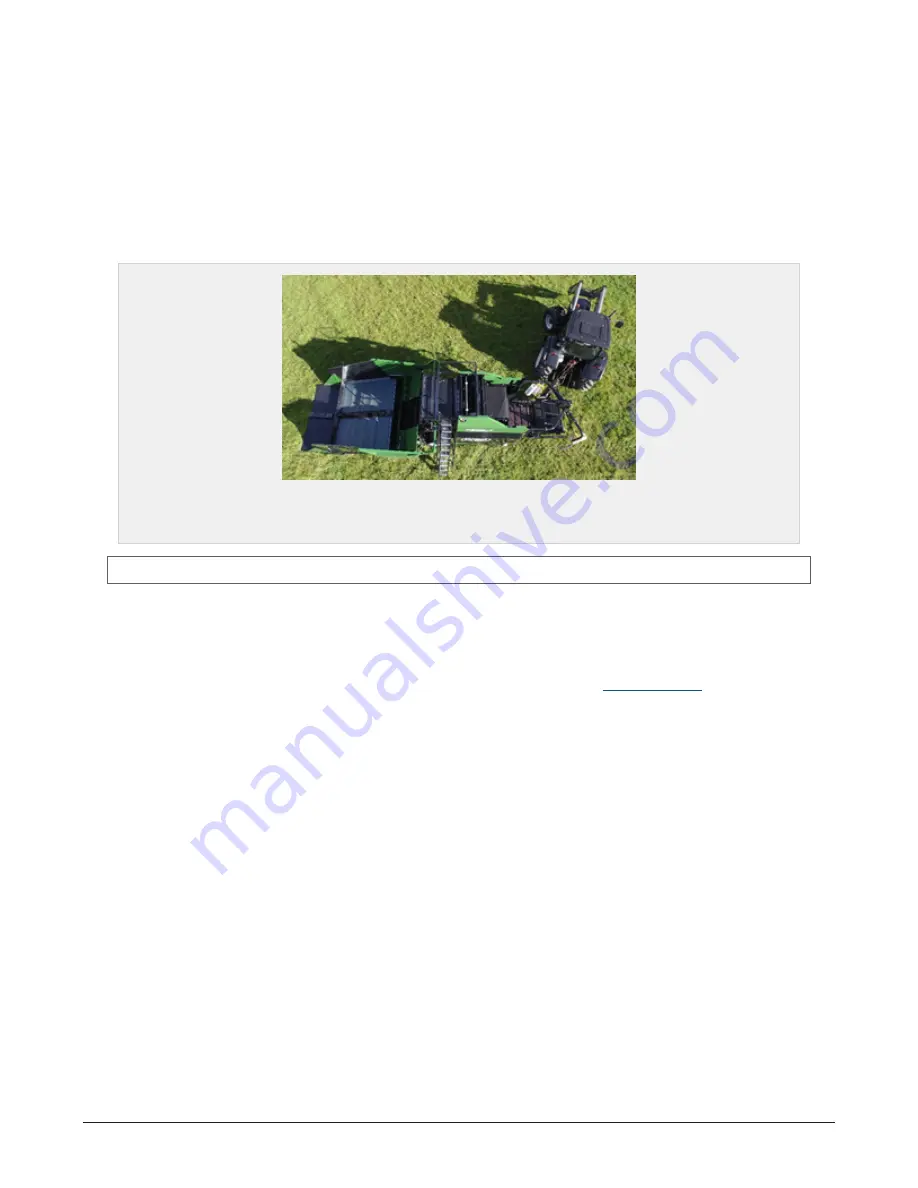
Figure 4.1 :
Tractor lineup. Ensure that the tractor is on the same line as the PTO shaft.
IMPORTANT: Flexible drawbar (tilting part) has to be in float position.
9. Continue levelling the machine with hydraulic jack stand, left- and right front (lever 7 and 8).
10. When levelling is done, operate the left and right part of the feed hopper OUT (lever 3 and 4). It is
important that both feed hopper parts are moved all the way out to their end position.
11. Sufficient clearance must be achieved between the hopper halves before lowering to down position
(limit switch active when sufficient). User resources are available at
12. Lower the left part of the feed hopper to DOWN position (lever 5).
13. Lower the right part of the feed hopper to DOWN position (lever 6).
14. Lower both feed hopper end flips (arrow down, rear controller).
15. Ensure that the tank valves are all open (T1-T5) (see
section 11.2.1 "Valve chart for Dens-X"
).
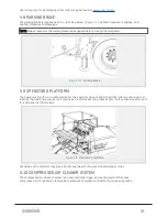
16. Fold down the stairs (see
).
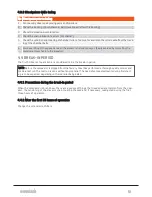
17. Start the tractors PTO. IMPORTANT: Check the rotational direction of the PTO (see
).
18. Run the PTO at about 300 RPM.
19. Maintain this speed until the oil has reached the appropriate operating temperature (see
).
20. Increase the speed to 850 RPM.
21. Lower the wrapping table to its horizontal position.
22. Fold down the bale bridge.
4 OPERATION
38
Summary of Contents for Dens-X Compactor
Page 14: ...1 6 DECLARATION OF CONFORMITY 1 GENERAL 14...
Page 103: ...8 7 MANUAL LUBRICATION CHARTS 8 7 1 The compactor 8 LUBRICATION 103...
Page 104: ...8 7 2 Feed hopper F25 8 LUBRICATION 104...
Page 105: ...8 7 3 Flexible drawbar 8 LUBRICATION 105...
Page 109: ...10 1 MAIN POWER SUPPLY E STOP SWITCHES AND ELECTRICAL CABINET 10 ELECTRICS 109...
Page 110: ...10 2 ELECTRICAL CABINET POWER SUPPLY RAIL 10 ELECTRICS 110...
Page 111: ...10 3 SENSORS AND MANUAL CONTROLS 10 ELECTRICS 111...
Page 112: ...10 4 VALVES FAN MOTORS AND PUMPS 10 ELECTRICS 112...
Page 124: ...10 9 SENSOR OVERVIEW 10 ELECTRICS 124...
Page 128: ...11 1 1 Complete diagram 11 HYDRAULICS 128...
Page 129: ...11 1 2 Wrapping table chamber and elevator control 11 HYDRAULICS 129...
Page 130: ...11 1 3 Plastic tying unit sub conveyor and feed hopper 11 HYDRAULICS 130...
Page 131: ...11 1 4 Additional feed hopper control for F25 and chamber drive 11 HYDRAULICS 131...
Page 133: ...11 2 VALVE OVERVIEW 11 2 1 Valve chart for Dens X 11 HYDRAULICS 133...
Page 137: ...12 6 3 Dimensional sketch F25 operating mode 12 SPECIFICATIONS 137...
Page 138: ...12 6 4 Dimensional sketch F25 transport mode 12 SPECIFICATIONS 138...
Page 142: ...M Maintenance 13 69 71 INDEX 142...

