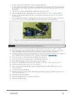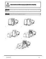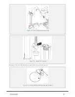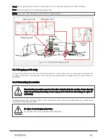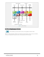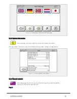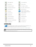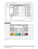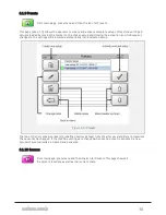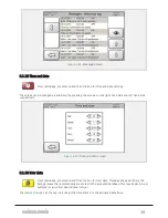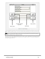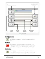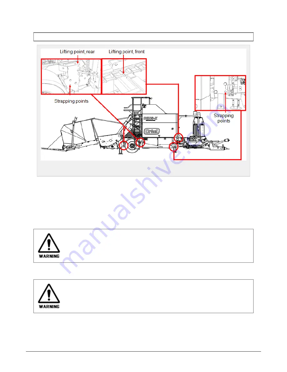
Front: Use a nylon strap to make a loop around the front crossbeam (Beam Dim: 100 x 100mm).
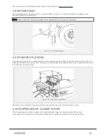
Rear: Use lifting points on the hydraulic jack stands
NOTE: Use only certified lifting gear with sufficient lifting capacity.
Figure 5.1 :
Lifting and strapping points
5.1.4 Strapping and tie down
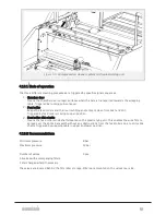
Secure the machine from moving if transported by lorry, train or boat. Only use approved securing straps
or chains, designed for this purpose. There are four points designed for strapping. One on each hydraulic
jack stand.
5.1.5 Dismantling the machine
General safety precautions must be taken when stripping down the machine. Center of gravity
might change during dismantling. Secure large parts to reduce the risk of injury. Be aware of
overturning.
Hazardous waste like: Oil, plastic and so on, must be stored in an environmentally safe way, or delivered at
a certified waste-disposal plant.
Be aware of overhanging power lines.
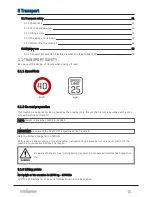
Max height in transport position: 3900 mm [F25]
5 TRANSPORT
52
Summary of Contents for Dens-X Compactor
Page 14: ...1 6 DECLARATION OF CONFORMITY 1 GENERAL 14...
Page 103: ...8 7 MANUAL LUBRICATION CHARTS 8 7 1 The compactor 8 LUBRICATION 103...
Page 104: ...8 7 2 Feed hopper F25 8 LUBRICATION 104...
Page 105: ...8 7 3 Flexible drawbar 8 LUBRICATION 105...
Page 109: ...10 1 MAIN POWER SUPPLY E STOP SWITCHES AND ELECTRICAL CABINET 10 ELECTRICS 109...
Page 110: ...10 2 ELECTRICAL CABINET POWER SUPPLY RAIL 10 ELECTRICS 110...
Page 111: ...10 3 SENSORS AND MANUAL CONTROLS 10 ELECTRICS 111...
Page 112: ...10 4 VALVES FAN MOTORS AND PUMPS 10 ELECTRICS 112...
Page 124: ...10 9 SENSOR OVERVIEW 10 ELECTRICS 124...
Page 128: ...11 1 1 Complete diagram 11 HYDRAULICS 128...
Page 129: ...11 1 2 Wrapping table chamber and elevator control 11 HYDRAULICS 129...
Page 130: ...11 1 3 Plastic tying unit sub conveyor and feed hopper 11 HYDRAULICS 130...
Page 131: ...11 1 4 Additional feed hopper control for F25 and chamber drive 11 HYDRAULICS 131...
Page 133: ...11 2 VALVE OVERVIEW 11 2 1 Valve chart for Dens X 11 HYDRAULICS 133...
Page 137: ...12 6 3 Dimensional sketch F25 operating mode 12 SPECIFICATIONS 137...
Page 138: ...12 6 4 Dimensional sketch F25 transport mode 12 SPECIFICATIONS 138...
Page 142: ...M Maintenance 13 69 71 INDEX 142...

