8 Lubrication
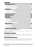
8.1 Lubrication system, beka max EP 1
8.1.1 Oil lubrication, mode of operation
8.1.2 Grease lubrication, mode of operation
8.1.3 Beka max grease lubrication system
8.2.1 Refilling the oil reservoir
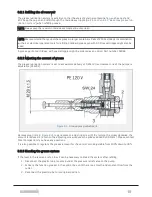
8.2.2 Adjusting the amount of grease
8.2.3 Bleeding the grease system
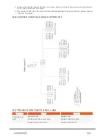
8.3 Electric pump and main distributor
8.4 Troubleshooting for Beka max
8.6.4 Gearbox and gears for hydraulic motors
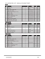
8.8 Lubrication list - Manual greasing points
8.1 LUBRICATION SYSTEM, BEKA MAX EP 1
The compactor is equipped with a fully automatic lubrication system. It lubricates the chamber roller bush-
ings (grease) and the chains (oil).
8.1.1 Oil lubrication, mode of operation
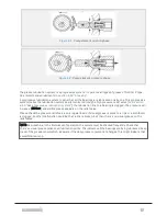
A single piston pump driven by the hydraulic pressure, supplies oil to the chains through brushes which are
mounted on strategic locations. Each time the chamber door opens, the piston is activated and supplies a
fixed amount of oil to the chains.
8.1.2 Grease lubrication, mode of operation
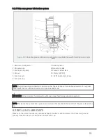
An electrical motor runs an eccentric disc. The eccentric disc drives two single working pistons which push
a fixed amount of grease through a pressure relief valve, and further on to a main distributor. The main dis-
tributor supplies grease to sub-distributors, which deliver the correct amount of grease to each bearing.
8 LUBRICATION
96
Summary of Contents for Dens-X Compactor
Page 14: ...1 6 DECLARATION OF CONFORMITY 1 GENERAL 14...
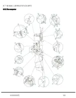
Page 103: ...8 7 MANUAL LUBRICATION CHARTS 8 7 1 The compactor 8 LUBRICATION 103...
Page 104: ...8 7 2 Feed hopper F25 8 LUBRICATION 104...
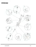
Page 105: ...8 7 3 Flexible drawbar 8 LUBRICATION 105...
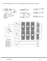
Page 109: ...10 1 MAIN POWER SUPPLY E STOP SWITCHES AND ELECTRICAL CABINET 10 ELECTRICS 109...
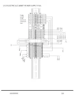
Page 110: ...10 2 ELECTRICAL CABINET POWER SUPPLY RAIL 10 ELECTRICS 110...
Page 111: ...10 3 SENSORS AND MANUAL CONTROLS 10 ELECTRICS 111...
Page 112: ...10 4 VALVES FAN MOTORS AND PUMPS 10 ELECTRICS 112...
Page 124: ...10 9 SENSOR OVERVIEW 10 ELECTRICS 124...
Page 128: ...11 1 1 Complete diagram 11 HYDRAULICS 128...
Page 129: ...11 1 2 Wrapping table chamber and elevator control 11 HYDRAULICS 129...
Page 130: ...11 1 3 Plastic tying unit sub conveyor and feed hopper 11 HYDRAULICS 130...
Page 131: ...11 1 4 Additional feed hopper control for F25 and chamber drive 11 HYDRAULICS 131...
Page 133: ...11 2 VALVE OVERVIEW 11 2 1 Valve chart for Dens X 11 HYDRAULICS 133...
Page 137: ...12 6 3 Dimensional sketch F25 operating mode 12 SPECIFICATIONS 137...
Page 138: ...12 6 4 Dimensional sketch F25 transport mode 12 SPECIFICATIONS 138...
Page 142: ...M Maintenance 13 69 71 INDEX 142...

