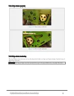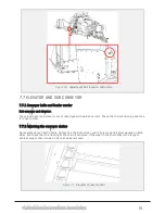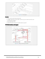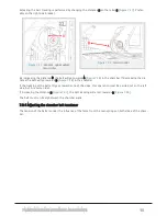
7.11 FRAME, DRAWBAR, ATTACHMENTS
7.11.1 Frame
Check the welding for cracks or deformations once a month.
7.11.2 Main components, fastening points
Check all major bolt connections and re-tighten if necessary.
l
Drawbar—frame
l
Drawbar—eye
l
Chamber—frame
l
Feed hopper—frame
l
Elevator—frame
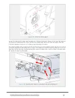
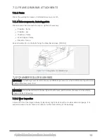
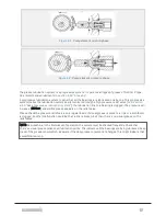
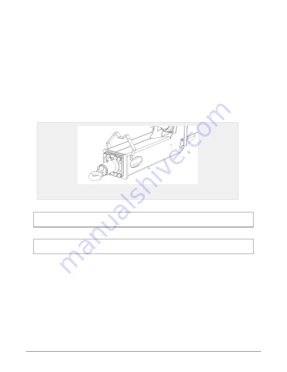
Pay extra attention to the bolts fixing the draw bar and eye. (574 Nm)
Figure 7.29 :
Fixing bolts for drawbar eye
7.12 CHAMBER ROLLER BUSHINGS
IMPORTANT: The bushings must be controlled every 5000 bales produced, or when 1000 hours of operation are
reached. Whatever comes first.
IMPORTANT: The distributed load to the bearings will not be even, and therefore the wear is not evenly dis-
tributed inside the bearing.
7.12.1 Wear inspection
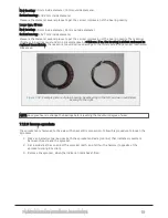
A quick control of the degree of wear (clearance) might be done with a crowbar and a dial gauge. If no
excessive wear is found, there’s no need for further dismantling of the bushings.
7 MAINTENANCE AND MECHANICAL ADJUSTMENTS
88
Summary of Contents for Dens-X Compactor
Page 14: ...1 6 DECLARATION OF CONFORMITY 1 GENERAL 14...
Page 103: ...8 7 MANUAL LUBRICATION CHARTS 8 7 1 The compactor 8 LUBRICATION 103...
Page 104: ...8 7 2 Feed hopper F25 8 LUBRICATION 104...
Page 105: ...8 7 3 Flexible drawbar 8 LUBRICATION 105...
Page 109: ...10 1 MAIN POWER SUPPLY E STOP SWITCHES AND ELECTRICAL CABINET 10 ELECTRICS 109...
Page 110: ...10 2 ELECTRICAL CABINET POWER SUPPLY RAIL 10 ELECTRICS 110...
Page 111: ...10 3 SENSORS AND MANUAL CONTROLS 10 ELECTRICS 111...
Page 112: ...10 4 VALVES FAN MOTORS AND PUMPS 10 ELECTRICS 112...
Page 124: ...10 9 SENSOR OVERVIEW 10 ELECTRICS 124...
Page 128: ...11 1 1 Complete diagram 11 HYDRAULICS 128...
Page 129: ...11 1 2 Wrapping table chamber and elevator control 11 HYDRAULICS 129...
Page 130: ...11 1 3 Plastic tying unit sub conveyor and feed hopper 11 HYDRAULICS 130...
Page 131: ...11 1 4 Additional feed hopper control for F25 and chamber drive 11 HYDRAULICS 131...
Page 133: ...11 2 VALVE OVERVIEW 11 2 1 Valve chart for Dens X 11 HYDRAULICS 133...
Page 137: ...12 6 3 Dimensional sketch F25 operating mode 12 SPECIFICATIONS 137...
Page 138: ...12 6 4 Dimensional sketch F25 transport mode 12 SPECIFICATIONS 138...
Page 142: ...M Maintenance 13 69 71 INDEX 142...


