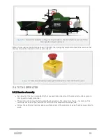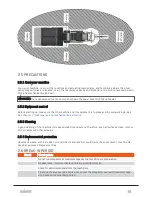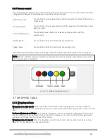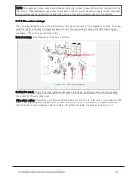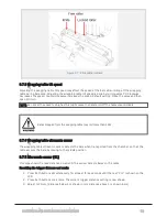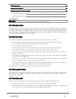
Figure 2.1 :
Red circles indicates emergency stop locations. Two more buttons are located on
the opposite side, ground level.
When an emergency stop button has been triggered, the emergency stop button has to be reset so that
the machine can be started from the control panel.
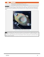
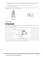
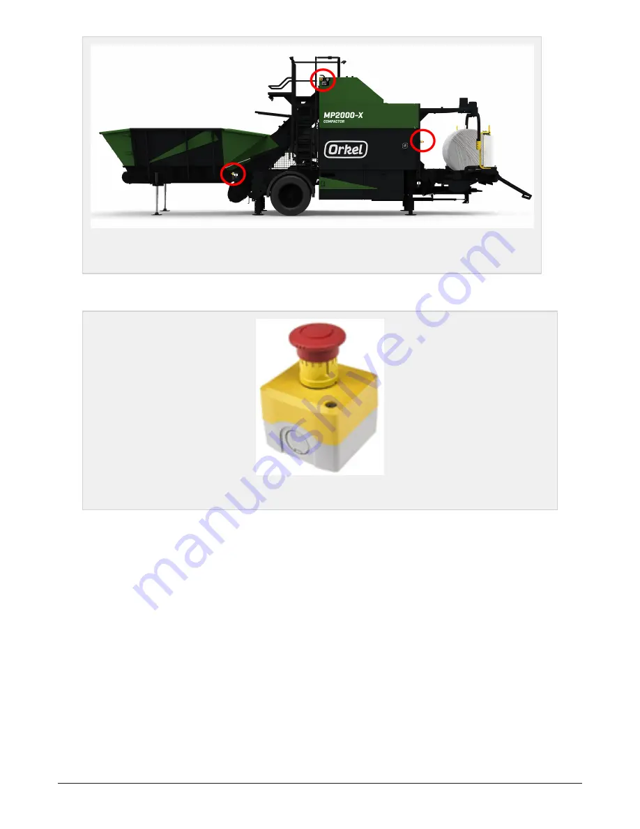
Figure 2.2 :
Mushroom head type emergency stop button. Twist the head to reset.
2.4 TO THE OPERATOR
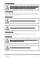
2.4.1 Exercise of security
l
As operator, it is your responsibility that you read and understand the safety instructions given in
this operator’s safety manual.
l
These instructions must be followed without exception. The operator is the key to safety on this
machine, not only for you, but also for others in the compactors working area.
l
Follow the safety instructions, and you will experience the compactor as a safe and secure place to
work.
2 SAFETY
18
Summary of Contents for MP2000-X
Page 14: ...1 6 DECLARATION OF CONFORMITY 1 GENERAL 14...
Page 98: ...8 6 4 Gearbox and gears for hydraulic motors Gear oil Renolin unisyn CLP 220N 8 LUBRICATION 98...
Page 99: ...8 7 MANUAL LUBRICATION CHARTS 8 7 1 The compactor 8 LUBRICATION 99...
Page 100: ...8 7 2 Feed hopper F10 8 LUBRICATION 100...
Page 101: ...8 7 3 Telescopic drawbar 8 LUBRICATION 101...
Page 105: ...10 1 MAIN POWER SUPPLY E STOP SWITCHES AND ELECTRICAL CABINET 10 ELECTRICS 105...
Page 106: ...10 2 ELECTRICAL CABINET POWER SUPPLY RAIL 10 ELECTRICS 106...
Page 107: ...10 3 SENSORS AND MANUAL CONTROLS 10 ELECTRICS 107...
Page 108: ...10 4 VALVES FAN MOTORS AND PUMPS 10 ELECTRICS 108...
Page 120: ...10 9 SENSOR OVERVIEW 10 ELECTRICS 120...
Page 124: ...11 1 1 Complete diagram 11 HYDRAULICS 124...
Page 125: ...11 1 2 Wrapping table chamber and elevator control 11 HYDRAULICS 125...
Page 128: ...11 2 VALVE OVERVIEW 11 2 1 Valve chart for MP2000 X 11 HYDRAULICS 128...
Page 132: ...12 6 3 Dimensional sketch F10 operating mode 12 SPECIFICATIONS 132...
Page 133: ...12 6 4 Dimensional sketch F10 transport mode 12 SPECIFICATIONS 133...
Page 137: ...M Maintenance 13 65 67 INDEX 137...

