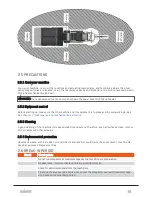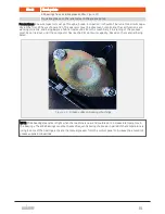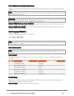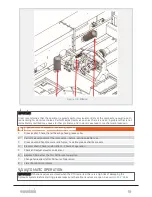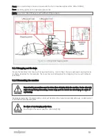
Take care when assembling/mounting the compactor. Squeezing of body parts and injuries from falling can
occur when maneuvering the wrapping table.
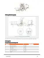
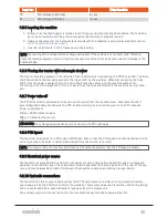
Max. height in operation position: 3900 mm
4.1.5 Elements of hazard during operation
If you fail to comply with instructions given it could result in personal injury or loss of life.
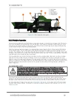
Pay attention to the risk of:
l
squeezing/crushing/cutting of fingers or hands near the knife for plastic tying unit.
l
squeezing/crushing of fingers or hands between conveyor belts and sprockets.
l
squeezing/crushing of fingers or hands between belt and roller, and under the wrapping table.
l
squeezing/crushing of body and feet when bale is dropped from the wrapping table.
l
squeezing/crushing of fingers or hands between wrapping arms and frame.
l
impact from rotating wrapping arms.
l
sensor on wrapping table might fail, causing a too early bale drop.
l
a burst in a hydraulic line/hose with high pressure- and heated oil can cause severe injury to eyes
and skin.
4.1.6 Danger zones during operation
The left side of the compactor is a blind spot. The operator must always be sure there’s no one present in
this area, before start up and during operation.
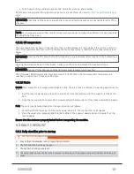
Maintain the boundaries of the danger zone as described in
.
4.1.7 Risk of overturning
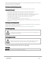
The operator must take precautions to avoid risk of overturning. Both during rigging, set-up
and when operating the machine.
4.1.8 Leaving the machine
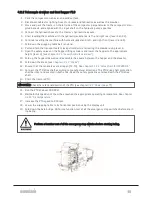
Before leaving the machine, the operator must turn off the engine (tractor) or any other
power source. Remove key or secure the power source to avoid unattended start.
4.2 CONNECTION AND SETTING UP THE MACHINE
4.2.1 Rig up
IMPORTANT: Be aware of the danger of tipping when rigging up.
4 OPERATION
34
Summary of Contents for MP2000-X
Page 14: ...1 6 DECLARATION OF CONFORMITY 1 GENERAL 14...
Page 98: ...8 6 4 Gearbox and gears for hydraulic motors Gear oil Renolin unisyn CLP 220N 8 LUBRICATION 98...
Page 99: ...8 7 MANUAL LUBRICATION CHARTS 8 7 1 The compactor 8 LUBRICATION 99...
Page 100: ...8 7 2 Feed hopper F10 8 LUBRICATION 100...
Page 101: ...8 7 3 Telescopic drawbar 8 LUBRICATION 101...
Page 105: ...10 1 MAIN POWER SUPPLY E STOP SWITCHES AND ELECTRICAL CABINET 10 ELECTRICS 105...
Page 106: ...10 2 ELECTRICAL CABINET POWER SUPPLY RAIL 10 ELECTRICS 106...
Page 107: ...10 3 SENSORS AND MANUAL CONTROLS 10 ELECTRICS 107...
Page 108: ...10 4 VALVES FAN MOTORS AND PUMPS 10 ELECTRICS 108...
Page 120: ...10 9 SENSOR OVERVIEW 10 ELECTRICS 120...
Page 124: ...11 1 1 Complete diagram 11 HYDRAULICS 124...
Page 125: ...11 1 2 Wrapping table chamber and elevator control 11 HYDRAULICS 125...
Page 128: ...11 2 VALVE OVERVIEW 11 2 1 Valve chart for MP2000 X 11 HYDRAULICS 128...
Page 132: ...12 6 3 Dimensional sketch F10 operating mode 12 SPECIFICATIONS 132...
Page 133: ...12 6 4 Dimensional sketch F10 transport mode 12 SPECIFICATIONS 133...
Page 137: ...M Maintenance 13 65 67 INDEX 137...

