l
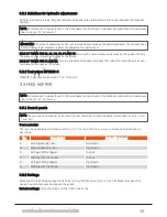
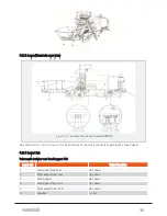
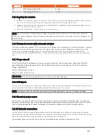
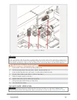
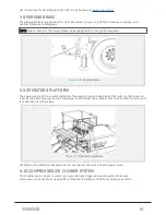
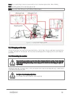
Feed hopper lifting cylinders, jack stands, film roller storage, and drawbar.
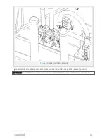
All functions are operated through manual levers on the machine. See
section 4.2.3 "Lever/Controls over-
IMPORTANT: Check that all the valves between the oil tank and hydraulic pumps are opened before the PTO is
started.
NOTE: For energy preservation flow rate from tractor should be set no higher than 30 l/min. Oil port should be
turned off when not in use.
4.2.11 Oil temperature
The oil temperature is shown in the top left corner on the display unit main page. If the oil is too cold, run
the PTO at maximum 300 rpm until the minimum start temperature is reached. See temperature values
below.
IMPORTANT: Starting the PTO drive shaft with full speed at a too low temperature may harm the hydraulic sys-
tem.
Heating the oil may take up to 25 minutes. A sticker on the oil tank indicates the applied oil type.
IMPORTANT: Run the PTO at 300 rpm until the minimum start temperature is reached.
Titan Transway WB: Minimum start temperature: 5°C / 50°F When the minimum start temperature is
reached, increase the PTO speed to 850 rpm.
4.2.12 Stairs
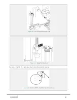
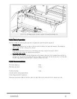
Unfold: The compactor is equipped with foldable stairs. The stair may be unfolded to working position as fol-
lows:
1. Pull the lever towards you and pull the stairs out from the machine until the support is fully exten-
ded.
2. Push the lever away from yourself and carefully fold the lower part of the stairs outwards and down.
Fold: The stair may be folded back into transport position as follows:
1. Carefully fold the lower part of the stairs upwards and in. Ensure that the lock engages.
2. Hold the upper stair segment and fold the middle of the support upwards and in. Ensure that the
lock engages.
Ensure that the stairs are properly locked before transporting the machine.
4.3 DAILY CHECKLIST
4.3.1 Daily checklist prior to startup
No Checkpoint prior to startup
1
Ensure that the drawbar is set in operational position.
2
Check that all main valves are open.
3
Check chain oil and grease level.
4
Check if grease comes out from the pressure relief valve on the grease pump unit (indicates blocking of
pipe).
4 OPERATION
38
Summary of Contents for MP2000-X
Page 14: ...1 6 DECLARATION OF CONFORMITY 1 GENERAL 14...
Page 98: ...8 6 4 Gearbox and gears for hydraulic motors Gear oil Renolin unisyn CLP 220N 8 LUBRICATION 98...
Page 99: ...8 7 MANUAL LUBRICATION CHARTS 8 7 1 The compactor 8 LUBRICATION 99...
Page 100: ...8 7 2 Feed hopper F10 8 LUBRICATION 100...
Page 101: ...8 7 3 Telescopic drawbar 8 LUBRICATION 101...
Page 105: ...10 1 MAIN POWER SUPPLY E STOP SWITCHES AND ELECTRICAL CABINET 10 ELECTRICS 105...
Page 106: ...10 2 ELECTRICAL CABINET POWER SUPPLY RAIL 10 ELECTRICS 106...
Page 107: ...10 3 SENSORS AND MANUAL CONTROLS 10 ELECTRICS 107...
Page 108: ...10 4 VALVES FAN MOTORS AND PUMPS 10 ELECTRICS 108...
Page 120: ...10 9 SENSOR OVERVIEW 10 ELECTRICS 120...
Page 124: ...11 1 1 Complete diagram 11 HYDRAULICS 124...
Page 125: ...11 1 2 Wrapping table chamber and elevator control 11 HYDRAULICS 125...
Page 128: ...11 2 VALVE OVERVIEW 11 2 1 Valve chart for MP2000 X 11 HYDRAULICS 128...
Page 132: ...12 6 3 Dimensional sketch F10 operating mode 12 SPECIFICATIONS 132...
Page 133: ...12 6 4 Dimensional sketch F10 transport mode 12 SPECIFICATIONS 133...
Page 137: ...M Maintenance 13 65 67 INDEX 137...

