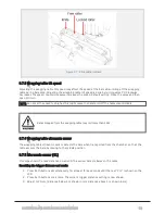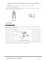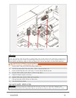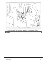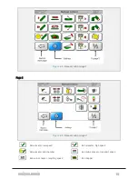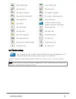
Figure 4.2 :
Filters
IMPORTANT:
Orkel recommends that the operator regularly performs visual controls of the compactor as well as act-
ive listening for abnormal noises. Perform adjustments as soon as there is a need. A problem that is not
immediately rectified may cause further problems, and in worst case lead to mechanical breakdown.
No Checkpoints during and after break-in period
1
Grease collar. Check that all bearings have grease collar.
2
Perform visual control of the compactor – before, during and after use.
3
Grease pump. Check pressure relief valve, no visible grease shall be present.
4
Elevator chain. Check tension after 1-3 hours of operation
5
Check and adjust elevator and sensor.
6
Replace filters after the first 50 hours of operation.
7
Change hydraulic oil after 50 hours of operation.
8
Listen for abnormal noises.
4.5 AUTOMATIC OPERATION
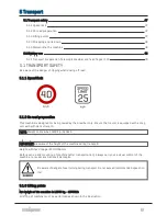
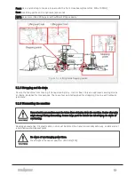
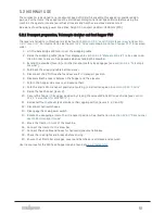
IMPORTANT: If the tank valves are closed when the PTO is started, there is a high risk of damaging the
hydraulic system. Before starting, please make sure that all tank valves are open. See
4 OPERATION
40
Summary of Contents for MP2000-X
Page 14: ...1 6 DECLARATION OF CONFORMITY 1 GENERAL 14...
Page 98: ...8 6 4 Gearbox and gears for hydraulic motors Gear oil Renolin unisyn CLP 220N 8 LUBRICATION 98...
Page 99: ...8 7 MANUAL LUBRICATION CHARTS 8 7 1 The compactor 8 LUBRICATION 99...
Page 100: ...8 7 2 Feed hopper F10 8 LUBRICATION 100...
Page 101: ...8 7 3 Telescopic drawbar 8 LUBRICATION 101...
Page 105: ...10 1 MAIN POWER SUPPLY E STOP SWITCHES AND ELECTRICAL CABINET 10 ELECTRICS 105...
Page 106: ...10 2 ELECTRICAL CABINET POWER SUPPLY RAIL 10 ELECTRICS 106...
Page 107: ...10 3 SENSORS AND MANUAL CONTROLS 10 ELECTRICS 107...
Page 108: ...10 4 VALVES FAN MOTORS AND PUMPS 10 ELECTRICS 108...
Page 120: ...10 9 SENSOR OVERVIEW 10 ELECTRICS 120...
Page 124: ...11 1 1 Complete diagram 11 HYDRAULICS 124...
Page 125: ...11 1 2 Wrapping table chamber and elevator control 11 HYDRAULICS 125...
Page 128: ...11 2 VALVE OVERVIEW 11 2 1 Valve chart for MP2000 X 11 HYDRAULICS 128...
Page 132: ...12 6 3 Dimensional sketch F10 operating mode 12 SPECIFICATIONS 132...
Page 133: ...12 6 4 Dimensional sketch F10 transport mode 12 SPECIFICATIONS 133...
Page 137: ...M Maintenance 13 65 67 INDEX 137...

