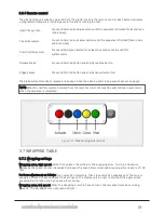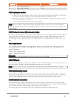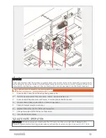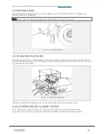
age. In order to operate the storages the machine must be connected to the tractor’s hydraulic system,
with the oil flow activated. The total capacity is 15 film rollers.
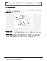
NOTE: 14 turns/laps of the wrapping arm equals approximately 6 layers of film on the bale.
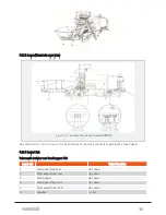
4.7 WRAPPING ARMS
4.7.1 Wrapping arm emergency stop
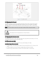
The compactors wrapping arms are equipped with safety guards that stop the wrappers movement if
obstructed while wrapping. If the safety guards are triggered, there will be a popup message on the dis-
play unit. The safety guards must be manually cleared from any obstruction. The machine will not start
until activated by a new command from the display unit.
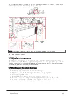
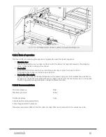
4.7.2 Installing a new film roller in the wrapper
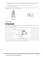
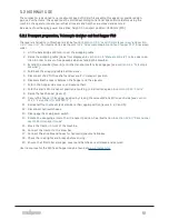
1. Grab the tensioner on the stretcher and pull it to the right.
2. Open the lock lever, lift the centering cone and lock it in its upper position.
3. Replace the empty film roller.
4. Align the film roller with the centering cone, drop and lock the cone.
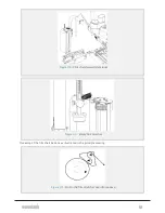
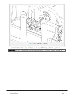
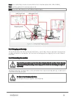
5. Thread the film as shown on
and swing back the tensioner onto the film roller.
6. Fasten the film on the bale or the film cutter. Wrapping may now continue.
4 OPERATION
42
Summary of Contents for MP2000-X
Page 14: ...1 6 DECLARATION OF CONFORMITY 1 GENERAL 14...
Page 98: ...8 6 4 Gearbox and gears for hydraulic motors Gear oil Renolin unisyn CLP 220N 8 LUBRICATION 98...
Page 99: ...8 7 MANUAL LUBRICATION CHARTS 8 7 1 The compactor 8 LUBRICATION 99...
Page 100: ...8 7 2 Feed hopper F10 8 LUBRICATION 100...
Page 101: ...8 7 3 Telescopic drawbar 8 LUBRICATION 101...
Page 105: ...10 1 MAIN POWER SUPPLY E STOP SWITCHES AND ELECTRICAL CABINET 10 ELECTRICS 105...
Page 106: ...10 2 ELECTRICAL CABINET POWER SUPPLY RAIL 10 ELECTRICS 106...
Page 107: ...10 3 SENSORS AND MANUAL CONTROLS 10 ELECTRICS 107...
Page 108: ...10 4 VALVES FAN MOTORS AND PUMPS 10 ELECTRICS 108...
Page 120: ...10 9 SENSOR OVERVIEW 10 ELECTRICS 120...
Page 124: ...11 1 1 Complete diagram 11 HYDRAULICS 124...
Page 125: ...11 1 2 Wrapping table chamber and elevator control 11 HYDRAULICS 125...
Page 128: ...11 2 VALVE OVERVIEW 11 2 1 Valve chart for MP2000 X 11 HYDRAULICS 128...
Page 132: ...12 6 3 Dimensional sketch F10 operating mode 12 SPECIFICATIONS 132...
Page 133: ...12 6 4 Dimensional sketch F10 transport mode 12 SPECIFICATIONS 133...
Page 137: ...M Maintenance 13 65 67 INDEX 137...

