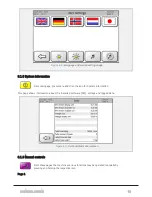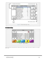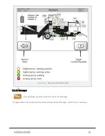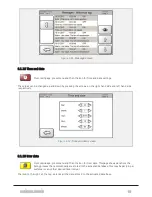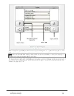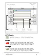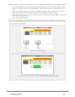
Figure 6.13 :
User data page
When pressing the upper left icon, the control unit generates a printable text file containing the customer
log.
NOTE: Insert the mini-USB-USB-adapter and flash drive into the control unit. The text file prints directly on
the flash drive when pressing the «generate»-button.
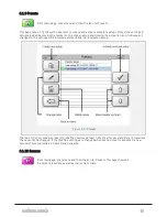
The icon in the lower right corner opens the user list, where customer databases can be created, activated
and deleted. The selected database can be activated by moving the marker to the desired database and
pressing the upper right icon.
6 CONTROL SYSTEM
60
Summary of Contents for MP2000-X
Page 14: ...1 6 DECLARATION OF CONFORMITY 1 GENERAL 14...
Page 98: ...8 6 4 Gearbox and gears for hydraulic motors Gear oil Renolin unisyn CLP 220N 8 LUBRICATION 98...
Page 99: ...8 7 MANUAL LUBRICATION CHARTS 8 7 1 The compactor 8 LUBRICATION 99...
Page 100: ...8 7 2 Feed hopper F10 8 LUBRICATION 100...
Page 101: ...8 7 3 Telescopic drawbar 8 LUBRICATION 101...
Page 105: ...10 1 MAIN POWER SUPPLY E STOP SWITCHES AND ELECTRICAL CABINET 10 ELECTRICS 105...
Page 106: ...10 2 ELECTRICAL CABINET POWER SUPPLY RAIL 10 ELECTRICS 106...
Page 107: ...10 3 SENSORS AND MANUAL CONTROLS 10 ELECTRICS 107...
Page 108: ...10 4 VALVES FAN MOTORS AND PUMPS 10 ELECTRICS 108...
Page 120: ...10 9 SENSOR OVERVIEW 10 ELECTRICS 120...
Page 124: ...11 1 1 Complete diagram 11 HYDRAULICS 124...
Page 125: ...11 1 2 Wrapping table chamber and elevator control 11 HYDRAULICS 125...
Page 128: ...11 2 VALVE OVERVIEW 11 2 1 Valve chart for MP2000 X 11 HYDRAULICS 128...
Page 132: ...12 6 3 Dimensional sketch F10 operating mode 12 SPECIFICATIONS 132...
Page 133: ...12 6 4 Dimensional sketch F10 transport mode 12 SPECIFICATIONS 133...
Page 137: ...M Maintenance 13 65 67 INDEX 137...

