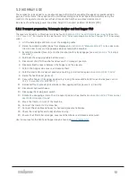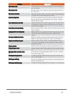
Before the software update, the new software must be copied onto the display unit by the following steps:
l
Place the software (zip archive) on an empty USB stick and insert the stick in the USB port on the
back of the display. Use a mini-USB-USB-adapter. The USB port is behind the black cap to the far
left.
l
Reboot the display unit by turning off the main power breaker at least 3 seconds. When the Orkel
logo shows, press and hold the lower right corner until ”Application Loader” is shown.
l
Press ”Update Software”, choose the software from the list and press ”Copy to Display”. Wait until
the status line shows ”Done”.
l
Press ”Run current Software”.
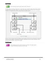
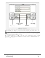
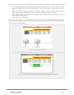
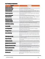
Tick off the boxes as shown to the right, and then click on the icon to start the update. When both green
progress bars show 100 %, restart the system by turning off the main power switch for at least 3 seconds.
The installation is now complete.
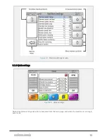
Figure 6.15 :
Software screen
Figure 6.16 :
Software screen. The green bars show that update is installing
6 CONTROL SYSTEM
62
Summary of Contents for MP2000-X
Page 14: ...1 6 DECLARATION OF CONFORMITY 1 GENERAL 14...
Page 98: ...8 6 4 Gearbox and gears for hydraulic motors Gear oil Renolin unisyn CLP 220N 8 LUBRICATION 98...
Page 99: ...8 7 MANUAL LUBRICATION CHARTS 8 7 1 The compactor 8 LUBRICATION 99...
Page 100: ...8 7 2 Feed hopper F10 8 LUBRICATION 100...
Page 101: ...8 7 3 Telescopic drawbar 8 LUBRICATION 101...
Page 105: ...10 1 MAIN POWER SUPPLY E STOP SWITCHES AND ELECTRICAL CABINET 10 ELECTRICS 105...
Page 106: ...10 2 ELECTRICAL CABINET POWER SUPPLY RAIL 10 ELECTRICS 106...
Page 107: ...10 3 SENSORS AND MANUAL CONTROLS 10 ELECTRICS 107...
Page 108: ...10 4 VALVES FAN MOTORS AND PUMPS 10 ELECTRICS 108...
Page 120: ...10 9 SENSOR OVERVIEW 10 ELECTRICS 120...
Page 124: ...11 1 1 Complete diagram 11 HYDRAULICS 124...
Page 125: ...11 1 2 Wrapping table chamber and elevator control 11 HYDRAULICS 125...
Page 128: ...11 2 VALVE OVERVIEW 11 2 1 Valve chart for MP2000 X 11 HYDRAULICS 128...
Page 132: ...12 6 3 Dimensional sketch F10 operating mode 12 SPECIFICATIONS 132...
Page 133: ...12 6 4 Dimensional sketch F10 transport mode 12 SPECIFICATIONS 133...
Page 137: ...M Maintenance 13 65 67 INDEX 137...

