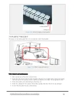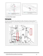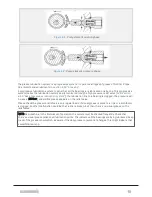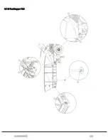
New bearing: 40 mm inside diameter, 44mm outside diameter.
Defect bearing: ≥ 42,2 mm inside diameter.
Measure the diameter several places to get the correct impression of the bearing ovality.
Large type, 50 mm
New bearing: 50 mm inside diameter, 55 mm outside diameter
Defect bearing: ≥ 52,7 mm inside diameter.
Measure the diameter several places to get the correct impression of the bearing ovality. The material
thickness in bearings must under no circumstances be ≤ 0,2 mm. If so, the bearing is defect and must be
replaced immediately. The reason is to avoid serious damage to the rollers axle, and potential mechanical
breakdown.
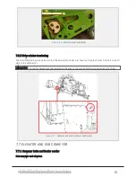
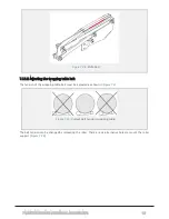
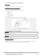
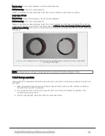
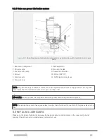
Figure 7.33 :
Example picture of plain bearing. New bearing to the left, and worn out/defect
bearing to the right.
NOTE: Good practice is to change the bearings before reaching the maximum degree of wear.
7.12.3 Remove sprockets
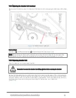
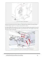
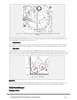
The sprockets are fastened to the axle with an eccentric connection. Follow this procedure to loosen the
sprockets.
1. Make an indication mark across both the sprocket and axle (red line) that indicates movement
between the axle and the sprocket.
2. Set a solid steel bar on one of the sprocket teeth, and hit it with a hammer (opposite of the
sprocket working direction).
3. Remove the sprocket, when the indication mark has shifted.
7 MAINTENANCE AND MECHANICAL ADJUSTMENTS
86
Summary of Contents for MP2000-X
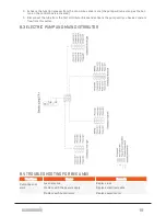
Page 14: ...1 6 DECLARATION OF CONFORMITY 1 GENERAL 14...
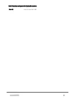
Page 98: ...8 6 4 Gearbox and gears for hydraulic motors Gear oil Renolin unisyn CLP 220N 8 LUBRICATION 98...
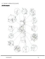
Page 99: ...8 7 MANUAL LUBRICATION CHARTS 8 7 1 The compactor 8 LUBRICATION 99...
Page 100: ...8 7 2 Feed hopper F10 8 LUBRICATION 100...
Page 101: ...8 7 3 Telescopic drawbar 8 LUBRICATION 101...
Page 105: ...10 1 MAIN POWER SUPPLY E STOP SWITCHES AND ELECTRICAL CABINET 10 ELECTRICS 105...
Page 106: ...10 2 ELECTRICAL CABINET POWER SUPPLY RAIL 10 ELECTRICS 106...
Page 107: ...10 3 SENSORS AND MANUAL CONTROLS 10 ELECTRICS 107...
Page 108: ...10 4 VALVES FAN MOTORS AND PUMPS 10 ELECTRICS 108...
Page 120: ...10 9 SENSOR OVERVIEW 10 ELECTRICS 120...
Page 124: ...11 1 1 Complete diagram 11 HYDRAULICS 124...
Page 125: ...11 1 2 Wrapping table chamber and elevator control 11 HYDRAULICS 125...
Page 128: ...11 2 VALVE OVERVIEW 11 2 1 Valve chart for MP2000 X 11 HYDRAULICS 128...
Page 132: ...12 6 3 Dimensional sketch F10 operating mode 12 SPECIFICATIONS 132...
Page 133: ...12 6 4 Dimensional sketch F10 transport mode 12 SPECIFICATIONS 133...
Page 137: ...M Maintenance 13 65 67 INDEX 137...

