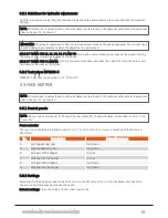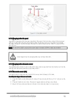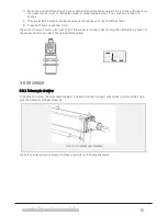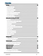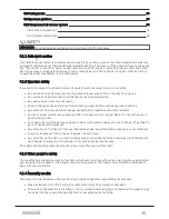
3.2.1 Guidelines for hydraulic adjustments
Specific instructions regarding hydraulic settings are listed and explained for each individual component
chapter.
NOTE: All references to valves found in this sub chapter can be found in the hydraulic schematic and valve over-
view in
IMPORTANT: All hydraulic adjustments: Start at low speed and increase the speed gradually. The oil must have
reached operating temperature when the adjustment is performed.
RULE OF THUMB FOR K1, B1, P2, P3, P4 AND P5: Turning the valve clockwise decreases the speed. Turning
the valve counterclockwise increases the speed.
RULE OF THUMB FOR P1 AND M1: Turning the valve clockwise increases the speed. Turning the valve coun-
terclockwise decreases the speed.
3.2.2 Tank valves MP2000-X
MP2000-X got four tank valves: T1, T2, T3 and T4.
3.3 FEED HOPPER
NOTE: All references to valves found in this sub chapter can be found in the hydraulic schematic and valve over-
view in
3.3.1 Control panels
NOTE: There is one control panel for F10, and no rear controller. The functionality is described in
.
Front controller
The levers are explained in detail in
section 4.2.3 "Lever/Controls overview"
and activate functions as
described.
No.
Description
Action/Movement
1.
Left support leg, rear
Up / down
2.
Right support leg, rear
Up / down
3.
Left part of the hopper
In / out
4.
Right part of the hopper
In / out
5.
Left part of the hopper
Up / down
6.
Right part of the hopper
Up / down
3.3.2 Settings
Adjusting the feed hopper speed is done by turning the M1 valve (
). Clockwise increases the
speed. Counterclockwise decreases the speed.
Default settings: Close the valve and then open two turns.
3 SETTINGS AND HYDRAULIC ADJUSTMENTS
24
Summary of Contents for MP2000-X
Page 14: ...1 6 DECLARATION OF CONFORMITY 1 GENERAL 14...
Page 98: ...8 6 4 Gearbox and gears for hydraulic motors Gear oil Renolin unisyn CLP 220N 8 LUBRICATION 98...
Page 99: ...8 7 MANUAL LUBRICATION CHARTS 8 7 1 The compactor 8 LUBRICATION 99...
Page 100: ...8 7 2 Feed hopper F10 8 LUBRICATION 100...
Page 101: ...8 7 3 Telescopic drawbar 8 LUBRICATION 101...
Page 105: ...10 1 MAIN POWER SUPPLY E STOP SWITCHES AND ELECTRICAL CABINET 10 ELECTRICS 105...
Page 106: ...10 2 ELECTRICAL CABINET POWER SUPPLY RAIL 10 ELECTRICS 106...
Page 107: ...10 3 SENSORS AND MANUAL CONTROLS 10 ELECTRICS 107...
Page 108: ...10 4 VALVES FAN MOTORS AND PUMPS 10 ELECTRICS 108...
Page 120: ...10 9 SENSOR OVERVIEW 10 ELECTRICS 120...
Page 124: ...11 1 1 Complete diagram 11 HYDRAULICS 124...
Page 125: ...11 1 2 Wrapping table chamber and elevator control 11 HYDRAULICS 125...
Page 128: ...11 2 VALVE OVERVIEW 11 2 1 Valve chart for MP2000 X 11 HYDRAULICS 128...
Page 132: ...12 6 3 Dimensional sketch F10 operating mode 12 SPECIFICATIONS 132...
Page 133: ...12 6 4 Dimensional sketch F10 transport mode 12 SPECIFICATIONS 133...
Page 137: ...M Maintenance 13 65 67 INDEX 137...

