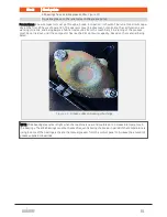
high density bale. The brake force should be set when net/film is pulled during the automatic net/film
sequence. The brake force is shown on the brake pressure gauge. The valve for the brake pressure is adjus-
ted consecutively until the appropriate brake force is reached. Start the adjustment with a low brake
force, and increase it. If the brake force is too high, this might damage or even rupture the net or film.
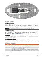
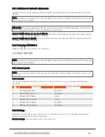
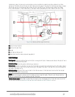
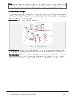
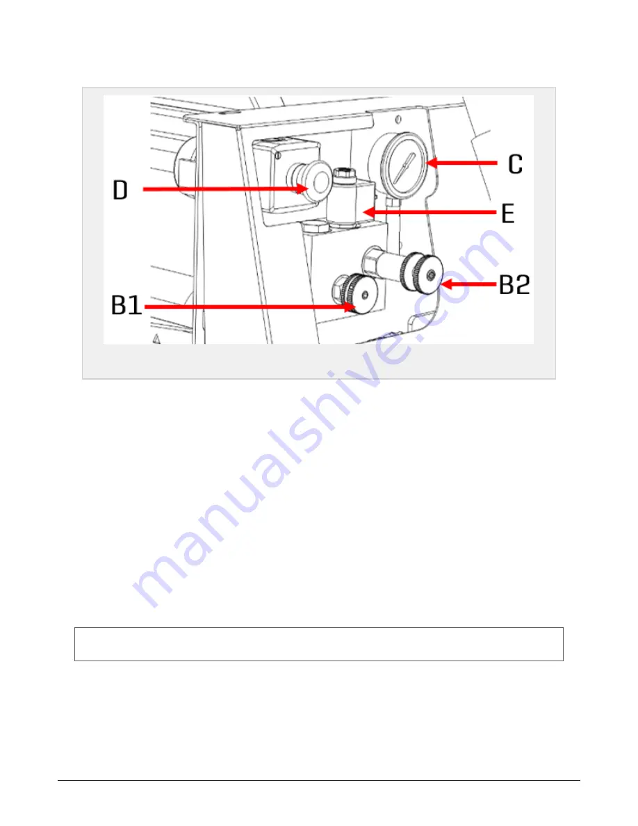
Figure 3.4 :
Brake and feed speed controls
B1 Valve for feed speed
B2 Valve for brake force
C Gauge
D Emergency stop switch
E Electrical valve for brake release/engagement
3.6.3 Settings
Feed speed: Adjusting the feed speed is done by turning the B1 valve. Clockwise decreases the speed. Coun-
terclockwise increases the speed.
Default setting: Close the valve and then open 3/4 turn.
Brake force: In order to maintain tension, the film roller is slowed down when being laid on the bale. Adjust-
ing this brake force is done by turning the B2 valve. Clockwise increases the brake force. Counterclockwise
decreases the brake force.
Default setting: Increase the pressure and notice the pressure on the manometer when the film breaks.
Then slightly decrease the pressure.
NOTE: When starting the machine cold, the brake pressure might be higher. Therefore, set the pressure by
cold oil or readjust when the oil temperature has increased.
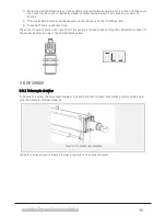
Brake release valve: The brake is controlled electrically from the display unit or from the remote control
on the platform. See
section 6.1.6 "Manual controls"
and
section 3.6.4 "Remote control"
3 SETTINGS AND HYDRAULIC ADJUSTMENTS
27
Summary of Contents for MP2000-X
Page 14: ...1 6 DECLARATION OF CONFORMITY 1 GENERAL 14...
Page 98: ...8 6 4 Gearbox and gears for hydraulic motors Gear oil Renolin unisyn CLP 220N 8 LUBRICATION 98...
Page 99: ...8 7 MANUAL LUBRICATION CHARTS 8 7 1 The compactor 8 LUBRICATION 99...
Page 100: ...8 7 2 Feed hopper F10 8 LUBRICATION 100...
Page 101: ...8 7 3 Telescopic drawbar 8 LUBRICATION 101...
Page 105: ...10 1 MAIN POWER SUPPLY E STOP SWITCHES AND ELECTRICAL CABINET 10 ELECTRICS 105...
Page 106: ...10 2 ELECTRICAL CABINET POWER SUPPLY RAIL 10 ELECTRICS 106...
Page 107: ...10 3 SENSORS AND MANUAL CONTROLS 10 ELECTRICS 107...
Page 108: ...10 4 VALVES FAN MOTORS AND PUMPS 10 ELECTRICS 108...
Page 120: ...10 9 SENSOR OVERVIEW 10 ELECTRICS 120...
Page 124: ...11 1 1 Complete diagram 11 HYDRAULICS 124...
Page 125: ...11 1 2 Wrapping table chamber and elevator control 11 HYDRAULICS 125...
Page 128: ...11 2 VALVE OVERVIEW 11 2 1 Valve chart for MP2000 X 11 HYDRAULICS 128...
Page 132: ...12 6 3 Dimensional sketch F10 operating mode 12 SPECIFICATIONS 132...
Page 133: ...12 6 4 Dimensional sketch F10 transport mode 12 SPECIFICATIONS 133...
Page 137: ...M Maintenance 13 65 67 INDEX 137...

