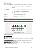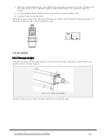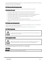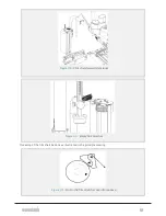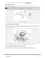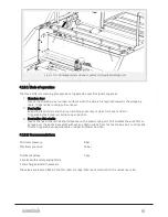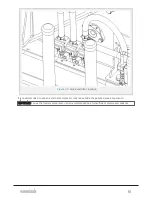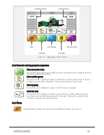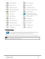
When pressing the start icon on the display unit, the following will happen:
The chamber starts, the elevator starts, the sub conveyor and hopper start. Material is fed into the bale
chamber. The feed amount is controlled by the ultrasonic sensor S29.
When set chamber pressure is reached (elevator slow threshold) the elevator slows down in order to
reduce the material flow into the chamber until the bale is finished.
Then, the net/film knife opens and the feed rollers start feeding the net/film into the chamber. A pre-
defined number of layers of net/film is laid on the bale, and the knife cuts the net/film.
The chamber opens and the bale is transported to the wrapper by the sub conveyor. The ultrasonic sensor
above the wrapping table detects the bale. Then the wrapping table receives the bale and tilts to its
middle position. The chamber door closes.
When the chamber door is closed, a new baling cycle starts. At the same time, the wrapping starts on the
wrapping table; the wrapping arms start and the film cutters release the film. The wrapping arms lay film
on the bale until a predefined number of revolutions is reached, before the film cutters cut the film.
The finished bale is then dropped from the wrapping table, either manually from the display unit, or auto-
matically if the automatic bale drop is activated.
There are several conditions that determine the desirable number of layers with wrapping film; type of
material, type of film and storage conditions and duration are especially important. Please read the
manual enclosed with the film.
NOTE: 14 turns/laps of the wrapping arm equals approximately 6 layers of film on the bale.
4.6 FILM ROLLER STORAGE
The compactor is equipped with two hydraulically operated film storages, one on each side behind the side
panels. Press and hold the activation switch and operate the lever up or down to raise or lower the stor-
4 OPERATION
41
Summary of Contents for MP2000-X
Page 14: ...1 6 DECLARATION OF CONFORMITY 1 GENERAL 14...
Page 98: ...8 6 4 Gearbox and gears for hydraulic motors Gear oil Renolin unisyn CLP 220N 8 LUBRICATION 98...
Page 99: ...8 7 MANUAL LUBRICATION CHARTS 8 7 1 The compactor 8 LUBRICATION 99...
Page 100: ...8 7 2 Feed hopper F10 8 LUBRICATION 100...
Page 101: ...8 7 3 Telescopic drawbar 8 LUBRICATION 101...
Page 105: ...10 1 MAIN POWER SUPPLY E STOP SWITCHES AND ELECTRICAL CABINET 10 ELECTRICS 105...
Page 106: ...10 2 ELECTRICAL CABINET POWER SUPPLY RAIL 10 ELECTRICS 106...
Page 107: ...10 3 SENSORS AND MANUAL CONTROLS 10 ELECTRICS 107...
Page 108: ...10 4 VALVES FAN MOTORS AND PUMPS 10 ELECTRICS 108...
Page 120: ...10 9 SENSOR OVERVIEW 10 ELECTRICS 120...
Page 124: ...11 1 1 Complete diagram 11 HYDRAULICS 124...
Page 125: ...11 1 2 Wrapping table chamber and elevator control 11 HYDRAULICS 125...
Page 128: ...11 2 VALVE OVERVIEW 11 2 1 Valve chart for MP2000 X 11 HYDRAULICS 128...
Page 132: ...12 6 3 Dimensional sketch F10 operating mode 12 SPECIFICATIONS 132...
Page 133: ...12 6 4 Dimensional sketch F10 transport mode 12 SPECIFICATIONS 133...
Page 137: ...M Maintenance 13 65 67 INDEX 137...

