5.2 HIGHWAY USE
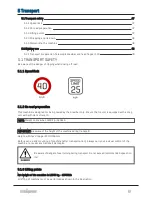
The compactor is designed for a maximum speed of 40 km/h. Exceeding this speed is considered dan-
gerous. Furthermore, the speed must be limited according to national speed limits. Before using the
machine the operator must ensure that all covers and hatches are closed and secured.
Be aware of overhanging power lines. Max. height in transport position: 4100 mm (F10)
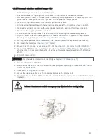
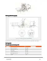
5.2.1 Transport preparation, Telescopic drawbar and feed hopper F10
The levers referred to in this chapter can be found in
section 4.2.3 "Lever/Controls overview"
and
. For illustrations, see
chapter 4.2.2 "Telescopic drawbar and feed hopper F10"
in reversed
order.
1. Lift the bale bridge and fold it over the wrapping table.
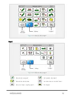
2. Raise the wrapping table (done from display unit,
section 6.1.6 "Manual controls"
) to its upper pos-
ition in order to ensure free passage when extending the drawbar.
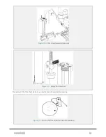
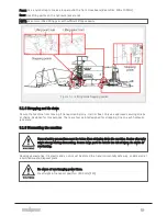
3. Extend the drawbar (lever 6) until the transport safety lock engages (see
).
4. Fold back the wrapping table belt tensioner.
5. Disconnect the PTO drive shaft and secure it in transport position.
6. Disassemble the covers between the hopper and the elevator.
7. Fold in the hopper side covers, and secure them.
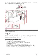
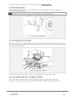
8. Fold the stairs into transport position, according to instructions given in
9. Raise the feed hopper (lever 3).
10. Secure the hopper in its upper position by closing the valves M2 and M3 on each side (see
11.2.1 "Valve chart for MP2000-X"
).
11. Retract all four hydraulic jack stands to their upper position (levers 1, 2, 4 and 5).
12. Disconnect hydraulic hoses.
13. Disengage the main power switch.
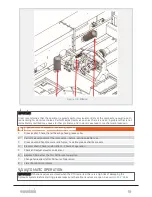
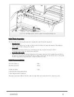
14. Rotate the wrapping arms to their transport position. See illustration in
15. Move the tractor in front of the machine.
16. Connect the tractor to the draw bar.
17. Connect the el-cable and hoses for hydraulic/pneumatic brakes.
18. Check the road lights and brakes before driving.
19. Ensure that film roller storages, covers and hatches are all closed and secured.
User resources for the F10 feed hopper may be found at
5 TRANSPORT
49
Summary of Contents for MP2000-X
Page 14: ...1 6 DECLARATION OF CONFORMITY 1 GENERAL 14...
Page 98: ...8 6 4 Gearbox and gears for hydraulic motors Gear oil Renolin unisyn CLP 220N 8 LUBRICATION 98...
Page 99: ...8 7 MANUAL LUBRICATION CHARTS 8 7 1 The compactor 8 LUBRICATION 99...
Page 100: ...8 7 2 Feed hopper F10 8 LUBRICATION 100...
Page 101: ...8 7 3 Telescopic drawbar 8 LUBRICATION 101...
Page 105: ...10 1 MAIN POWER SUPPLY E STOP SWITCHES AND ELECTRICAL CABINET 10 ELECTRICS 105...
Page 106: ...10 2 ELECTRICAL CABINET POWER SUPPLY RAIL 10 ELECTRICS 106...
Page 107: ...10 3 SENSORS AND MANUAL CONTROLS 10 ELECTRICS 107...
Page 108: ...10 4 VALVES FAN MOTORS AND PUMPS 10 ELECTRICS 108...
Page 120: ...10 9 SENSOR OVERVIEW 10 ELECTRICS 120...
Page 124: ...11 1 1 Complete diagram 11 HYDRAULICS 124...
Page 125: ...11 1 2 Wrapping table chamber and elevator control 11 HYDRAULICS 125...
Page 128: ...11 2 VALVE OVERVIEW 11 2 1 Valve chart for MP2000 X 11 HYDRAULICS 128...
Page 132: ...12 6 3 Dimensional sketch F10 operating mode 12 SPECIFICATIONS 132...
Page 133: ...12 6 4 Dimensional sketch F10 transport mode 12 SPECIFICATIONS 133...
Page 137: ...M Maintenance 13 65 67 INDEX 137...

