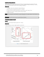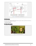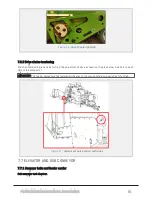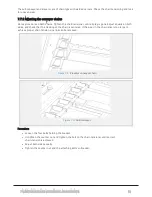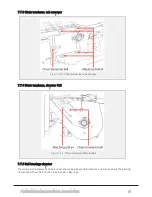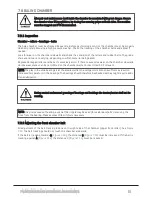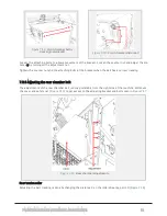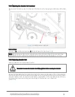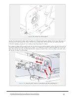
Implications during adjustment:
When adjusting either the left side (drive chain tension) or the right side (belt tracking) of this roller,
these adjustments influence each other. Hence, you have to adjust both sides multiple times, until you
achieve the ultimate chain tension and belt tracking combination.
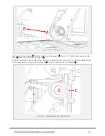
Adjustment:
1. Untighten the two bolts holding the adjustable bracket.
2. Adjust the chain tension by turning the nut on the bolt.
3. Tighten the bolts holding the adjustable bracket when the chain-tension is OK.
4. Readjust the right side to find the optimal lining of the belt.
5. Repeat if necessary.
NOTE: Right side adjustment (belt tracking) is done by following the same general steps as described above.
IMPORTANT: Check the chain tension after adjusting the belt tracking.
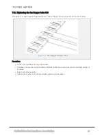
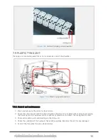
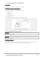
7.4.2 Chain tensioner B and C
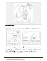
Control:
The length of the spring should be between 130 - 140mm.
Adjustment:
Increase the chain tension by tightening the nut on the bolt.
Figure 7.2 :
Chain tensioner B and C
7 MAINTENANCE AND MECHANICAL ADJUSTMENTS
69
Summary of Contents for MP2000-X
Page 14: ...1 6 DECLARATION OF CONFORMITY 1 GENERAL 14...
Page 98: ...8 6 4 Gearbox and gears for hydraulic motors Gear oil Renolin unisyn CLP 220N 8 LUBRICATION 98...
Page 99: ...8 7 MANUAL LUBRICATION CHARTS 8 7 1 The compactor 8 LUBRICATION 99...
Page 100: ...8 7 2 Feed hopper F10 8 LUBRICATION 100...
Page 101: ...8 7 3 Telescopic drawbar 8 LUBRICATION 101...
Page 105: ...10 1 MAIN POWER SUPPLY E STOP SWITCHES AND ELECTRICAL CABINET 10 ELECTRICS 105...
Page 106: ...10 2 ELECTRICAL CABINET POWER SUPPLY RAIL 10 ELECTRICS 106...
Page 107: ...10 3 SENSORS AND MANUAL CONTROLS 10 ELECTRICS 107...
Page 108: ...10 4 VALVES FAN MOTORS AND PUMPS 10 ELECTRICS 108...
Page 120: ...10 9 SENSOR OVERVIEW 10 ELECTRICS 120...
Page 124: ...11 1 1 Complete diagram 11 HYDRAULICS 124...
Page 125: ...11 1 2 Wrapping table chamber and elevator control 11 HYDRAULICS 125...
Page 128: ...11 2 VALVE OVERVIEW 11 2 1 Valve chart for MP2000 X 11 HYDRAULICS 128...
Page 132: ...12 6 3 Dimensional sketch F10 operating mode 12 SPECIFICATIONS 132...
Page 133: ...12 6 4 Dimensional sketch F10 transport mode 12 SPECIFICATIONS 133...
Page 137: ...M Maintenance 13 65 67 INDEX 137...

