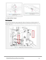
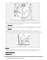
background image

7.8 BALING CHAMBER

All repair and maintenance work inside the chamber is associated with great danger. Secure
the chamber door lifting cylinders, by closing the securing valves on both sides. The machine
must be stopped and PTO disconnected.
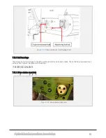
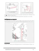
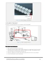
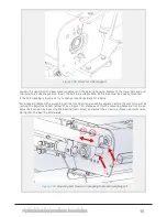
7.8.1 Inspection

Chamber - rollers - bearings - belts

The bale chamber must be checked frequently. Before performing a control, the chamber must be properly
cleaned, preferable using a high pressure washer. Check the tracking of the chamber belts and adjust if
needed.

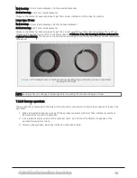
Look for wear on the chamber sidewalls and check the condition of the rollers and rubber belts. The grade
of wear and tear are varying, depending on which material being baled.

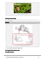
Replace damaged rollers and belts if excessively worn. If there is excessive wear on the chamber sidewalls,
Hardox wear plates can be retrofitted on the chamber walls. Contact Orkel AS if relevant.

NOTE: The play in the slide bearings is at the smallest when the compactor is brand new. This may result in
increased temperature in the bearings. The bearings should therefore be checked as they might require addi-
tional lubrication.

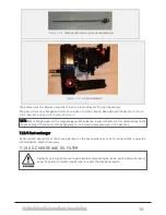
During control and manual greasing of bearings and bushings the tractor/motor shall not be
running.

NOTE: In extreme cases of heating, a special filler nipple may be used (force lubricate) after removing the
hose from the bearing. Please contact Orkel if this is necessary.

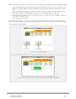
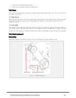
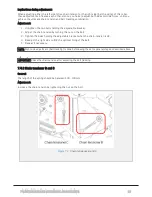
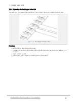
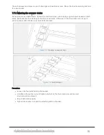
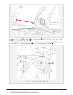
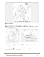
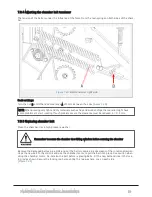
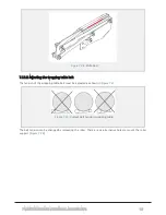
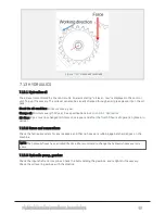
7.8.2 Adjusting the front chamber belt

All adjustment of the belt tracking is done on the right side of the chamber (upper front roller). See

Figure

7.13

. The belt tracking should not touch the chamber side walls.

If the belt is tracking towards B (

Figure 7.12

), the distance C (

Figure 7.13

) must be increased. If the belt is

tracking against A (

Figure 7.12

) the distance C (

Figure 7.13

) must be reduced.

7 MAINTENANCE AND MECHANICAL ADJUSTMENTS

75

Summary of Contents for MP2000-X

Page 1: ...Rev MP2000 X UM 2A EN Original version Published 2020 According to Directive 2006 42 EC Annex 1 7 4 1 Orkel AS Johan Gj nnes veg 25 7320 Fannrem Norway Valid from serial number 20427005 Orkel part num...

Page 2: ...s manual 13 1 5 Warranty 13 1 6 Declaration of conformity 14 2 Safety 15 2 1 Introduction 15 2 2 Symbols 15 2 2 1 Warning danger and caution 15 2 3 Emergency stop 17 2 4 To the operator 18 2 4 1 Exerc...

Page 3: ...yor 25 3 4 1 Settings 25 3 5 Chamber 25 3 5 1 Opening speed settings 25 3 5 2 Chamber pressure settings 25 3 6 Plastic tying unit 26 3 6 1 Principle of operation 26 3 6 2 Brake and feed speed 26 3 6 3...

Page 4: ...2 5 Leveling the machine 37 4 2 6 Placing the tractor with telescopic drawbar 37 4 2 7 Power take off 37 4 2 8 PTO Speed 37 4 2 9 Electrical power source 37 4 2 10 Hydraulic connections 37 4 2 11 Oil...

Page 5: ...machine 48 5 2 Highway use 49 5 2 1 Transport preparation Telescopic drawbar and feed hopper F10 49 6 Control system 50 6 1 User interface 50 6 1 1 Main page 50 6 1 2 Icons for starting program sequen...

Page 6: ...Chain tensioner A 68 7 4 2 Chain tensioner B and C 69 7 5 Feed hopper 70 7 5 1 Tightening the feed hopper belts F10 70 7 5 2 Ball bearings 71 7 6 Drive chains 71 7 6 1 Drive chains overview 71 7 6 2 D...

Page 7: ...ion 84 7 12 2 Permissible wear 85 7 12 3 Remove sprockets 86 7 13 Hydraulics 87 7 13 1 Hydraulics oil 87 7 13 2 Hoses and connections 87 7 13 3 Hydraulic pump gearbox 87 7 13 4 Heat exchanger 88 7 14...

Page 8: ...rts 99 8 7 1 The compactor 99 8 7 2 Feed hopper F10 100 8 7 3 Telescopic drawbar 101 8 8 Lubrication list Manual greasing points 102 9 Preservation 103 9 1 Cleaning 103 9 1 1 Using high pressure washe...

Page 9: ...nd switches 117 10 8 3 Directional valves 117 10 8 4 Sensors 7 lead cable 118 10 8 5 Film system remote control 118 10 8 6 Radio remote control 118 10 8 7 Proportional valves 118 10 8 8 Valves 118 10...

Page 10: ...ff 130 12 3 Lubrication system beka max 130 12 4 Hydraulic system 131 12 5 Wheels and tyres 131 12 6 Dimensions and weight 131 12 6 1 Measurements 131 12 6 2 Power requirements 131 12 6 3 Dimensional...

Page 11: ...zation of the machine With regards Orkel AS 1 1 2 Disclaimer The original parts used in an Orkel machine are designed and built to provide optimal fit function safety and structural integrity For this...

Page 12: ...se both in handling and operating the compactor will be held at site if requested agreed During commissioning and start up period we re offering our technical assistance and answering all questions re...

Page 13: ...scribes the rig up process what to consider prior to and during operation It also spe cifies the running in period 5 TRANSPORT States all the safety measures and preparations necessary for successful...

Page 14: ...1 6 DECLARATION OF CONFORMITY 1 GENERAL 14...

Page 15: ...ther hand it is not possible to describe every operational and safety matters that may arise Care fully consider all your actions if it is posing a safety hazard to you or others close to the compacto...

Page 16: ...e things Danger rotating parts Keep clear of moving rotating parts in chamber Operator or others close to the machine must be aware when the bale is unloaded from the wrapper table Bales dropped may r...

Page 17: ...cking the tail gate lifting cylinders Between the tractor and the machine there is a rotating PTO shaft No one is allowed to stand between the tractor and the machine while the engine is running Do no...

Page 18: ...y stop button Twist the head to reset 2 4 TO THE OPERATOR 2 4 1 Exercise of security l As operator it is your responsibility that you read and understand the safety instructions given in this operator...

Page 19: ...peration If pressing of flammable mater ials a fire extinguisher must be in close proximity 2 4 4 Safe operation Persons under 16 years of age should under no circumstances operate this machine Person...

Page 20: ...intenance and mechanical adjustments 2 5 3 Cleaning A good cleaning of the machine increases durability and safety Therefore keep all surfaces clean remove dirt oil spills and other remains 2 5 4 Envi...

Page 21: ...normal sounds from the machinery Fine tuning of the process must be carried out until the compactor has reached its optimum capacity based on the material being baled Figure 2 3 Grease collar on beari...

Page 22: ...gs 25 3 5 Chamber 25 3 5 1 Opening speed settings 25 3 5 2 Chamber pressure settings 25 3 6 Plastic tying unit 26 3 6 1 Principle of operation 26 3 6 2 Brake and feed speed 26 3 6 3 Settings 27 3 6 4...

Page 23: ...e machine runs on the automatic sequence The operator s main task is to ensure that there is a sufficient amount of material in the hopper and that the finished bales are moved away from the bale drop...

Page 24: ...0 X MP2000 X got four tank valves T1 T2 T3 and T4 3 3 FEED HOPPER NOTE All references to valves found in this sub chapter can be found in the hydraulic schematic and valve over view in chapter 11 Hydr...

Page 25: ...er view in chapter 11 Hydraulics 3 5 1 Opening speed settings Closing speed Adjusting the bale chamber closing speed is done by turning the K1 valve Clockwise decreases the speed Counterclockwise incr...

Page 26: ...s of net lm Afterwards the feed rollers close again and the net lm is cut by the knife Finally the chamber door opens and the bale is transported to the wrapper by the sub conveyor The chamber closes...

Page 27: ...eases the speed Coun terclockwise increases the speed Default setting Close the valve and then open 3 4 turn Brake force In order to maintain tension the film roller is slowed down when being laid on...

Page 28: ...e when the opening and closing sequences are engaged NOTE When the net film system is started from the remote control the machine will continue in auto mode when the sequence is completed Figure 3 5 P...

Page 29: ...e reduced by turning the valve clockwise Both cutters should be equally set The cutters should move softly Default setting Close the valve and then open 1 2 turn Figure 3 6 Film cutter valves Setting...

Page 30: ...from the wrapping table may roll more than 10 m 3 7 4 Wrapping table ultrasonic sensor The wrapping table ultrasonic sensor detects the bale when transported from the chamber so that the table accepts...

Page 31: ...t time The sensor shows its state in its right LED If the sensor is OK and reads nothing the LED will shine green If the sensor detects an object the LED will shine yellow 3 8 DRAWBAR 3 8 1 Telescopic...

Page 32: ...36 4 2 5 Leveling the machine 37 4 2 6 Placing the tractor with telescopic drawbar 37 4 2 7 Power take off 37 4 2 8 PTO Speed 37 4 2 9 Electrical power source 37 4 2 10 Hydraulic connections 37 4 2 1...

Page 33: ...tential danger caused by the machines automatic systems l carry out a test on emergency stop switches and sensors on a regular basis to ensure they are in good working order l shut down the machine be...

Page 34: ...frame l impact from rotating wrapping arms l sensor on wrapping table might fail causing a too early bale drop l a burst in a hydraulic line hose with high pressure and heated oil can cause severe inj...

Page 35: ...see chapter 4 2 3 Lever Controls overview 10 Fold up the hopper side walls and assemble the covers between the hopper and the elevator 11 Fold down the stairs see chapter 4 2 12 Stairs 12 Ensure that...

Page 36: ...ions of the levers controls regarding the feed hopper 4 2 4 Lever list Telescopic drawbar and feed hopper F10 Lever no Valve function 1 Left support leg rear Up down 2 Right support leg rear Up down 3...

Page 37: ...r take off The PTO drive shaft is delivered with its own user manual from the manufacturer Assemble the shaft accordingly Maintain and lubricate the PTO shaft according to instructions given in the PT...

Page 38: ...Titan Transway WB Minimum start temperature 5 C 50 F When the minimum start temperature is reached increase the PTO speed to 850 rpm 4 2 12 Stairs Unfold The compactor is equipped with foldable stair...

Page 39: ...belts 6 Avoid overfilling of the space between the elevator and sub conveyor Easily avoided by controlling the material amount fed into the elevator 4 4 BREAK IN PERIOD The first 50 hours of operatio...

Page 40: ...ollar 2 Perform visual control of the compactor before during and after use 3 Grease pump Check pressure relief valve no visible grease shall be present 4 Elevator chain Check tension after 1 3 hours...

Page 41: ...door closes When the chamber door is closed a new baling cycle starts At the same time the wrapping starts on the wrapping table the wrapping arms start and the film cutters release the film The wrap...

Page 42: ...e will be a popup message on the dis play unit The safety guards must be manually cleared from any obstruction The machine will not start until activated by a new command from the display unit 4 7 2 I...

Page 43: ...3 Film stretcher with tensioner Figure 4 4 Empty film strecher Threading of the film shall be done as illustrated in the principle drawing Figure 4 5 Film in the film stretcher seen from above 4 OPER...

Page 44: ...form is a safe station for the operator when changing net film rollers in the tying unit It keeps the operator away from all moving parts and makes the process safer It also contains extra room for ad...

Page 45: ...Triggered by feed rollers moving to open position 3 Feed roller slide shafts Cleans the feed rollers slide shafts located on the plastic tying unit This enables the wide film to spread over the entire...

Page 46: ...lter location It is recommended to use an external compressor located outside the polluted area of operation IMPORTANT To use the tractors compressor is not recommended due to insufficient compressor...

Page 47: ...owed by the drawbar only Ensure the tractor is equipped with a drag unit with sufficient strength NOTE Weight on draw bar 1640 Kg 3600Lb IMPORTANT Be aware of the height of the machine during transpor...

Page 48: ...raps or chains designed for this purpose There are four points designed for strapping One on each hydraulic jack stand 5 1 5 Dismantling the machine General safety precautions must be taken when strip...

Page 49: ...8 1 Telescopic drawbar 4 Fold back the wrapping table belt tensioner 5 Disconnect the PTO drive shaft and secure it in transport position 6 Disassemble the covers between the hopper and the elevator...

Page 50: ...n provides a brief introduction to the user interface so that you quickly can get started using the machine NOTE Software reviewed by this chapter is 0 17 03 Variations from the illustrations may occu...

Page 51: ...lays net or film on the bale in the chamber Afterwards the machine continues in auto mode Start wrapping This icon starts a complete sequence in which the bale is wrapped Start bale drop This icon sta...

Page 52: ...n page press menu and then the icon for Language and screen settings Choose the desired language The system will remember which language is chosen and use it as default The screen s brightness as well...

Page 53: ...n for System information This page shows information about the installed software SW voltage and logged data Figure 6 4 System information screen 6 1 6 Manual controls From these pages the machine s v...

Page 54: ...trol page 1 Page 2 Figure 6 6 Manual control page 2 Run elevator low speed Run elevator high speed Run elevator and chamber Run sub conveyor transport speed Run sub conveyor recycling speed Run hopper...

Page 55: ...brake off on Run wrapping table belt Start bale drod Reverse cooler fan self cleaning Sound warning siren Flash signal tower Run grease pump 6 1 7 Machine settings From main page press Menu and then t...

Page 56: ...6 7 Machine settings screen 6 1 8 Quick settings Figure 6 8 Quick settings Certain machine settings can also be accessed from the main page also when the machine is running in auto mode 6 CONTROL SYS...

Page 57: ...ngs will be stored automatically in the selected setup Figure 6 9 Presets The top of the list contains presets predefined factory setups from Orkel for several different materials These cannot be chan...

Page 58: ...sor overview with status 6 1 11 Messages From main page press menu and then the icon for Messages This page shows a list containing the previous 100 operational messages including error messages 6 CON...

Page 59: ...ft hand side respectively Figure 6 12 Time and date screen 6 1 13 User data From main page press menu and then the icon for User data This page shows data from the baling process that automatically ar...

Page 60: ...and flash drive into the control unit The text file prints directly on the flash drive when pressing the generate button The icon in the lower right corner opens the user list where customer databases...

Page 61: ...aling process so that this starts from the beginning when the machine is put in auto mode The reset does not affect the settings nor the stored user data 6 1 16 Software From main page press menu and...

Page 62: ...el logo shows press and hold the lower right corner until Application Loader is shown l Press Update Software choose the software from the list and press Copy to Display Wait until the status line sho...

Page 63: ...Counted from completed feeding Laps of wrapping film Defines whether the system stops upon failure of wrapping sequence known as Film control US trigger distance Defines the number of rounds of film...

Page 64: ...the wrapping table belts rotates during the bale drop If activated the bale may roll further away from the machine Bale eject additional rotation Defines an additional rotation of the bale when ejecte...

Page 65: ...7 6 Drive chains 71 7 6 1 Drive chains overview 71 7 6 2 Drive chains tensioning 72 7 7 Elevator and sub conveyor 72 7 7 1 Conveyor belts and feeder carrier 72 7 7 2 Adjusting the conveyor chains 73 7...

Page 66: ...Before any maintenance or adjustments are performed on the machine we recommend you to make a con ference call to your local dealer or Orkel AS All repair work shall be carried out by a skilled mecha...

Page 67: ...C 158 F IMPORTANT Safeguard can only be dismounted when the machine is stopped 7 1 4 Control after repair or maintenance Check that all tools are stowed away and that all covers are mounted correctly...

Page 68: ...before transport to a new location See section 12 5 Wheels and tyres 7 4 CHAINS The chamber chains and chain tensioner A B and C must be controlled for sufficient lubrication and cor rect tension Look...

Page 69: ...g the nut on the bolt 3 Tighten the bolts holding the adjustable bracket when the chain tension is OK 4 Readjust the right side to find the optimal lining of the belt 5 Repeat if necessary NOTE Right...

Page 70: ...neven wear Figure 7 3 Feed hopper conveyor F10 Procedure l Loosen the four bolts holding the bracket l Untighten the counter nut and tighten the bolt on the chain tensioner until correct belt tension...

Page 71: ...e rollers in the feed hopper should be without deformations and cracks Check the bearing clearances without belt tension Replace worn bearings 7 6 DRIVE CHAINS 7 6 1 Drive chains overview Figure 7 5 D...

Page 72: ...e pics below One bolt on each side of the compactor IMPORTANT The hopper halves must be lowered all the way to the ground before one can adjust the chain Figure 7 7 Adjustment bolt location both sides...

Page 73: ...cking of the chain is centered If the wear in the chain links is too large to achieve proper chain tension one link can be removed Figure 7 8 Elevator conveyor chain Figure 7 9 Sub conveyor Procedure...

Page 74: ...sioner elevator F10 Figure 7 11 Chain tensioner F10 elevator 7 7 5 Ball bearings elevator The rollers in the elevator and belt under should be without deformations and cracks Check the bearing clearan...

Page 75: ...n be retrofitted on the chamber walls Contact Orkel AS if relevant NOTE The play in the slide bearings is at the smallest when the compactor is brand new This may result in increased temperature in th...

Page 76: ...ket when the belt has a correct tracking 7 8 3 Adjusting the rear chamber belt The adjustments of the rear chamber belt is done preferably from the right side of the machine Dismount the cover and saf...

Page 77: ...tance C the belt tracking will go towards A If the belt still goes towards one of the sides this operation must be carried out on the left side bearings but in reverse order If reducing the distance...

Page 78: ...ent roller Figure 7 19 Tension roller By increasing the distance D the belt will go towards A Figure 7 19 in the chamber If decreasing the dis tance the belt will go towards B Figure 7 19 in the chamb...

Page 79: ...the clearance must be reduced A 0 1mm 7 8 5 Replacing chamber belt Clean the chamber Use a high pressure washer Remember to secure the chamber door lifting cylinders before entering the chamber Remove...

Page 80: ...or feed rollers 2 Check the chain tension and the chain condition SeeFigure 7 23 Adjust the tension by loosening the bolt and turn the nylon eccentric to add more tension to the chain Then retighten t...

Page 81: ...top handles Tighten the hinge bolts so that the handles barely returns to the start position If the hinge bolts are too loose the emergency stop handles may be triggered unnecessary Also check that th...

Page 82: ...wrapping table belt must be adjusted as shown in Figure 7 27 Figure 7 27 Correct belt tension wrapping table The belt tension can be changed by relocating the roller There are six alternative holes to...

Page 83: ...location side of the belts For wrapping tables with a weighing cell the front belt tension can be adjusted within the slot arrow 1 by turning the adjustment bolt arrow 2 see Figure 7 29 Because of thi...

Page 84: ...xing bolts for drawbar eye 7 12 CHAMBER ROLLER BUSHINGS IMPORTANT The bushings must be controlled every 5000 bales produced or when 1000 hours of operation are reached Whatever comes first IMPORTANT T...

Page 85: ...er side 2 Drive chain This condition occurs on the bushings that are affected by the drive chain direction A turning point is shown in Figure 7 32 The wear is also influenced by the chamber pressure B...

Page 86: ...damage to the rollers axle and potential mechanical breakdown Figure 7 33 Example picture of plain bearing New bearing to the left and worn out defect bearing to the right NOTE Good practice is to ch...

Page 87: ...8 6 1 Hydraulics Oil filter 3 pcs must be changed minimum once a year and after the first 50 hours of operation break in period 7 13 2 Hoses and connections Check the hydraulic system for any leakages...

Page 88: ...st be cleaned Inspect the amount of metal shavings on the magnetic plug If there s a lot of shavings present it s indicating excessive wear in the gear box 7 13 4 Heat exchanger Perform daily inspecti...

Page 89: ...filter according to the Filter procedure below 10 Drain the oil and remove the oil filter on the collector according to the Collector and cooler pro cedure 11 Refill A sticker on the oil tank indicate...

Page 90: ...the drain hole 4 Remove the drain plug 5 Drain until empty 6 Clean the magnetic plug 7 Mount the gear in its original position 8 Refill with Shell Omala S2 220 9 Reinsert the plug 7 15 WELDING AND GRI...

Page 91: ...othes Always keep a fire extinguisher available 7 16 SERVICE HISTORY We recommend to fill in all service maintenance work in this table Date year Service maintenance major repair Performed by Name com...

Page 92: ...8 Lubrication list Manual greasing points 102 8 1 LUBRICATION SYSTEM BEKA MAX EP 1 The compactor is equipped with a fully automatic lubrication system It lubricates the chamber roller bush ings grease...

Page 93: ...on line to a bearing is clogged the pressure will increase 280 bar and visible grease appears on the relief valve Please check the pressure relief valve on a regular basis If visual grease is present...

Page 94: ...lain bearings on chamber rollers are under huge stress and force during operation It is of great importance that the lubrication system is in good working order IMPORTANT Do not operate the compactor...

Page 95: ...ase The grease lubrication system is set to a maximum delivery of 0 29cm rev However one of the pumps is adjustable PE120V Figure 8 4 Grease pump adjustment Remove plug item 2 Figure 8 4 to get access...

Page 96: ...from the first distributor block and activate the pump until you have a constant flow from this outlet 8 3 ELECTRIC PUMP AND MAIN DISTRIBUTOR 8 4 TROUBLESHOOTING FOR BEKA MAX Problems Cause Remedy Pum...

Page 97: ...tem check Run greaser manually for one minute 1 or 2 times to lubricate the system Then restart machine and verify that the greas ing system operates as intended Grease on pressure relief valve System...

Page 98: ...8 6 4 Gearbox and gears for hydraulic motors Gear oil Renolin unisyn CLP 220N 8 LUBRICATION 98...

Page 99: ...8 7 MANUAL LUBRICATION CHARTS 8 7 1 The compactor 8 LUBRICATION 99...

Page 100: ...8 7 2 Feed hopper F10 8 LUBRICATION 100...

Page 101: ...8 7 3 Telescopic drawbar 8 LUBRICATION 101...

Page 102: ...ollers 4 Left and right 8 W 9 Cylinder wrapping table 2 Left and right 4 W 10 Wrapping table 3 Left and right 6 W 11 Knife arms wrapping table 6 Left and right 12 W 12 Wrapping table support roller 1...

Page 103: ...rage period Touch up paint is recommended to avoid corrosion 9 2 1 Long time storage If you re using grease of NLGI class 2 with EP additives extreme pressure there s no need for special pre cautions...

Page 104: ...r supply 112 10 6 1 Supply block 1 112 10 6 2 Supply block 2 113 10 7 Inputs and outputs sorted by number 114 10 7 1 IO list 1 114 10 7 2 IO list 2 115 10 7 3 IO list 3 116 10 8 Inputs and outputs sor...

Page 105: ...10 1 MAIN POWER SUPPLY E STOP SWITCHES AND ELECTRICAL CABINET 10 ELECTRICS 105...

Page 106: ...10 2 ELECTRICAL CABINET POWER SUPPLY RAIL 10 ELECTRICS 106...

Page 107: ...10 3 SENSORS AND MANUAL CONTROLS 10 ELECTRICS 107...

Page 108: ...10 4 VALVES FAN MOTORS AND PUMPS 10 ELECTRICS 108...

Page 109: ...e DO 1 2 X1 17 V19 Net feed motor DO 1 2 X1 18 V35 Air cleaning door OPT DO 1 2 X1 19 S17 Chamber opened DI Bk Bl Br X1 20 S18 Chamber closed DI Bk Bl Br X1 21 NOT IN USE X1 22 NOT IN USE X1 23 Sensor...

Page 110: ...Chamber pressure AI Wh Br X3 6 S29 Feed hopper US sensor AI Gy Bl Br X3 7 S44 Feed hopper start DI C Gn X3 8 S45 Feed hopper stop DI C R X3 9 NOT IN USE X3 10 F25 control supply 5V REF C Br X3 11 NOT...

Page 111: ...21 NOT IN USE X5 22 NOT IN USE X5 23 Sensor supply DO X X 10 5 5 IO block 6 Loc ID Description Type Hi Mid Low X6 1 V30 Wrapper speed PWM 1 X6 2 NOT IN USE X6 3 V30 Wrapper speed FB FB 2 X6 4 NOT IN...

Page 112: ...Stop OPT DI Wh X7 17 Cable detection DI X13 2 X7 18 NOT IN USE X7 19 S11 Film sensor 1 PI A Bl X7 20 S12 Film sensor 2 PI A Gn X7 21 S34 RF remote ctrl Drop OPT DI Bk X7 22 S46 RF remote ctrl Aux OPT...

Page 113: ...bus high 870 831 X13 14 CANbus low 870 831 X13 15 CANbus low 870 831 10 6 2 Supply block 2 Left Middle left Middle Middle right Right Left W guard valve Display unit Br To X13 9 To X13 5 Cooler fan R...

Page 114: ...UTPUTS SORTED BY NUMBER 10 7 1 IO list 1 All sensors ID Description Loc Type Hi Mid Low S01 Bale on wrapping table X5 19 DI A Wh S03 Table middle position X5 20 DI Bk Bl Br S05 Wrapping arm home posit...

Page 115: ...IC3 ID Description Loc Type Hi Mid Low V01 Sub conveyor bypass X2 1 DO 1 2 V02 Chamber open X1 1 DO 1 2 V03 Chamber close X1 2 DO 1 2 V04 Wrapper bypass off X1 3 DO 1 2 V05 Table up X5 1 DO 1 2 V06 Ta...

Page 116: ...k right X6 6 DO 1 2 V55 Flip check left X6 7 DO 1 2 V56 Auger bypass X5 16 DO 1 2 10 8 INPUTS AND OUTPUTS SORTED BY TYPE 10 8 1 Inductive sensors Inductive sensors ID Description Loc Hi Mid Low S03 Ta...

Page 117: ...onveyor bypass X2 1 1 2 V02 Chamber open X1 1 1 2 V03 Chamber close X1 2 1 2 V04 Wrapper bypass off X1 3 1 2 V05 Table up X5 1 1 2 V06 Table down X5 2 1 2 V07 Run wrapping table X5 3 1 2 V08 Net knife...

Page 118: ...control Radio remote control ID Description Loc Hi Mid Low S33 RF remote ctrl Stop OPT X7 16 Wh S34 RF remote ctrl Drop OPT X7 21 Bk S46 RF remote ctrl Aux OPT X7 22 Gy 10 8 7 Proportional valves Pro...

Page 119: ...direction X6 5 1 2 V54 Flip check right X6 6 1 2 V55 Flip check left X6 7 1 2 V56 Auger bypass X5 16 1 2 10 8 9 Cable detection Cable detection Automatic controller identification ID Description Loc...

Page 120: ...10 9 SENSOR OVERVIEW 10 ELECTRICS 120...

Page 121: ...PNP Pepperl Fuchs NBB8 18GM50 E2 V1 3 8 mm S18 Chamber closed position Inductive PNP Pepperl Fuchs NBB8 18GM50 E2 V1 3 8 mm S19 Feed rollers open position Inductive PNP Pepperl Fuchs NBB8 18GM50 E2 V...

Page 122: ...ote control flip up Switch NO F25 only S43 Remote control flip down Switch NO F25 only S44 Remote control hopper start Switch NO F25 only S45 Remote control hopper stop Switch NO F25 only S46 RF Remot...

Page 123: ...unit sub conveyor and feed hopper 126 11 1 4 Hydraulic diagram list 126 11 2 Valve overview 128 11 2 1 Valve chart for MP2000 X 128 11 2 2 Valve list for MP2000 X 129 11 1 HYDRAULIC DIAGRAM Please ref...

Page 124: ...11 1 1 Complete diagram 11 HYDRAULICS 124...

Page 125: ...11 1 2 Wrapping table chamber and elevator control 11 HYDRAULICS 125...

Page 126: ...4Vdc Resistance in Ohms Comment V1 Digital valve Comatrol SV 15 34 04 1 38 A 17 V2 Digital valve Comatrol SV 15 34 05 1 38 A 17 V3 Digital valve Comatrol SV 15 34 05 1 38 A 17 V4 Digital valve Comatro...

Page 127: ...Comatrol PSV10 NC 0 9 A 200 mA min 16 V31 Buzzer Fulleon ROLP SV W S 32 mA V32 Servo solenoid Samhydraulik SH6V 0 68 A 230 mA min 24 6 V33 Relay Bosch 0 332 209 206 896 0 1 A 215 Sinking output V34 R...

Page 128: ...11 2 VALVE OVERVIEW 11 2 1 Valve chart for MP2000 X 11 HYDRAULICS 128...

Page 129: ...opper speed In cabinet on valve block M2 Feed hopper transport safety valve Feed hopper cylinder right hand side M3 Feed hopper transport safety valve Feed hopper cylinder left hand side P1 Wrapper sp...

Page 130: ...18GM50 E2 V1 Feed hopper Ultrasonic analogue Pepperl Fuchs UC2000 30GM70 IE2R2 V15 Wrapping table Ultrasonic digital 70 cm def Microsonic mic 130 D TC Oil temperature PT1000 FuehlerSysteme EF5 E 20 5...

Page 131: ...lb in Wheel nuts torque 450 Nm 12 6 DIMENSIONS AND WEIGHT 12 6 1 Measurements Net weight F10 telescopic drawbar 9660 kg Allowed total weight 12500 kg Allowed vertical load on drawbar 2500 kg Height F...

Page 132: ...12 6 3 Dimensional sketch F10 operating mode 12 SPECIFICATIONS 132...

Page 133: ...12 6 4 Dimensional sketch F10 transport mode 12 SPECIFICATIONS 133...

Page 134: ...the feed hopper to the chamber F Feed hopper The feed hopper is made for loading material into which is fed into the chamber via the elevator It is mounted at the back of the compactor and comes in se...

Page 135: ...on the wrapping table by rotating the arms around the bale Safety features are mounted on the arms so that the emergency stop is triggered if something hits the safety features Wrapping table The wrap...

Page 136: ...55 D Daily checklist 38 F Film roller Installing a new film roller 42 H How to use this manual 13 Hydraulics Recommended grease 97 Recommended oil types 23 Valve chart 128 L Lubrication Approved lubr...

Page 137: ...M Maintenance 13 65 67 INDEX 137...

Reviews: