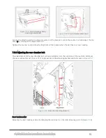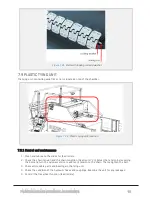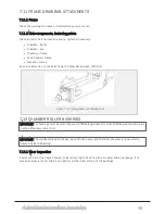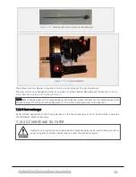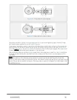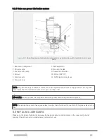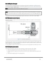
4. Drain until empty.
5. Clean the oil spill.
6. Mount the new filter.
7. Dispose with the old filter according to environmental regulations.
IMPORTANT: Always use original parts when changing filter.
Changing gear oil
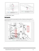
For main gear, feed hopper, elevator and wrapping table:
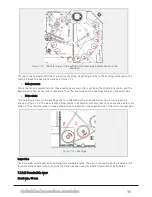
1. Place an empty container beneath the drain hole.
2. Remove the drain plug.
3. Drain until empty.
4. Clean the plug.
5. Clean up the oil spill.
6. Reinsert the plug (replace sealing if necessary).
7. Refill with Shell Omala S2 220.
8. Check the oil level.
Sub-conveyor gear
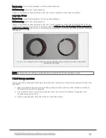
1. Remove the gear from the compactor.
2. Rotate (drain plug down).
3. Place an empty container beneath the drain hole.
4. Remove the drain plug.
5. Drain until empty.
6. Clean the magnetic plug.
7. Mount the gear in its original position.
8. Refill with Shell Omala S2 220.
9. Reinsert the plug.
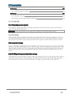
7.15 WELDING AND GRINDING
DISCLAIMER: Changes made to the frame may invalidate warranty and homologation standards. By doing so
you may forfeit warranty claims. Any changes to the frame or machine should be avoided if possible.
All welding, drilling and other work done on the frame, must be carried out with great caution.
7.15.1 Precautions when welding
IMPORTANT: The control unit must be disconnected before welding.
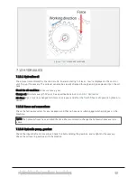
Place the ground connector as close to the welding point as possible. Observe excessive temperatures.
NOTE: After grinding/cutting/welding, repaint the areas in order to avoid corrosion.
7 MAINTENANCE AND MECHANICAL ADJUSTMENTS
90
Summary of Contents for MP2000-X
Page 14: ...1 6 DECLARATION OF CONFORMITY 1 GENERAL 14...
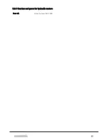
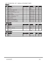
Page 98: ...8 6 4 Gearbox and gears for hydraulic motors Gear oil Renolin unisyn CLP 220N 8 LUBRICATION 98...
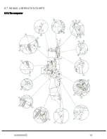
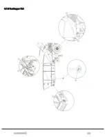
Page 99: ...8 7 MANUAL LUBRICATION CHARTS 8 7 1 The compactor 8 LUBRICATION 99...
Page 100: ...8 7 2 Feed hopper F10 8 LUBRICATION 100...
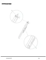
Page 101: ...8 7 3 Telescopic drawbar 8 LUBRICATION 101...
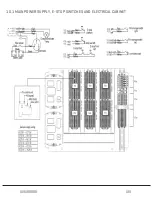
Page 105: ...10 1 MAIN POWER SUPPLY E STOP SWITCHES AND ELECTRICAL CABINET 10 ELECTRICS 105...
Page 106: ...10 2 ELECTRICAL CABINET POWER SUPPLY RAIL 10 ELECTRICS 106...
Page 107: ...10 3 SENSORS AND MANUAL CONTROLS 10 ELECTRICS 107...
Page 108: ...10 4 VALVES FAN MOTORS AND PUMPS 10 ELECTRICS 108...
Page 120: ...10 9 SENSOR OVERVIEW 10 ELECTRICS 120...
Page 124: ...11 1 1 Complete diagram 11 HYDRAULICS 124...
Page 125: ...11 1 2 Wrapping table chamber and elevator control 11 HYDRAULICS 125...
Page 128: ...11 2 VALVE OVERVIEW 11 2 1 Valve chart for MP2000 X 11 HYDRAULICS 128...
Page 132: ...12 6 3 Dimensional sketch F10 operating mode 12 SPECIFICATIONS 132...
Page 133: ...12 6 4 Dimensional sketch F10 transport mode 12 SPECIFICATIONS 133...
Page 137: ...M Maintenance 13 65 67 INDEX 137...

