IG-267-EN versión 01; 07/04/2017
63
General Instructions
ekor
.rpa
Protection, metering and control models
8.2.3. Installation in a cubicle
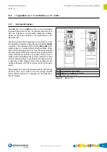
The components of the
ekor
.rpa-110-v and
ekor
.rpa-120-v
units are the electronic relay, voltage and current
sensors, bistable tripping device (Binox), tripping coil and
interconnection terminal block.
The electronic relay is secured to the cubicle driving
mechanism with anchors. The front of the device, which
houses the components of the user interface, display, keys,
mini-USB port, etc., is accessible from the outside without
the need to remove the mechanism enclosure.
The connectors for the relay (Relay Terminal Block), which
interconnects with the driving mechanism connectors
(Terminal Block-A) and the current and voltage sensors
(Terminal Block-G: Test blocks for voltage and current
injection) are located in the top of the relay and at the back
of the driving mechanism.
The cubicle with the integrated
ekor
.rpa-100 unit
interconnects with other cubicles, with the power units and
with the remote control unit using interconnection sleeves
(communications and power bus). This interconnection
feeds the different cubicle devices (relay, coils, motors, etc.)
and closes the substation's local communications bus.
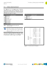
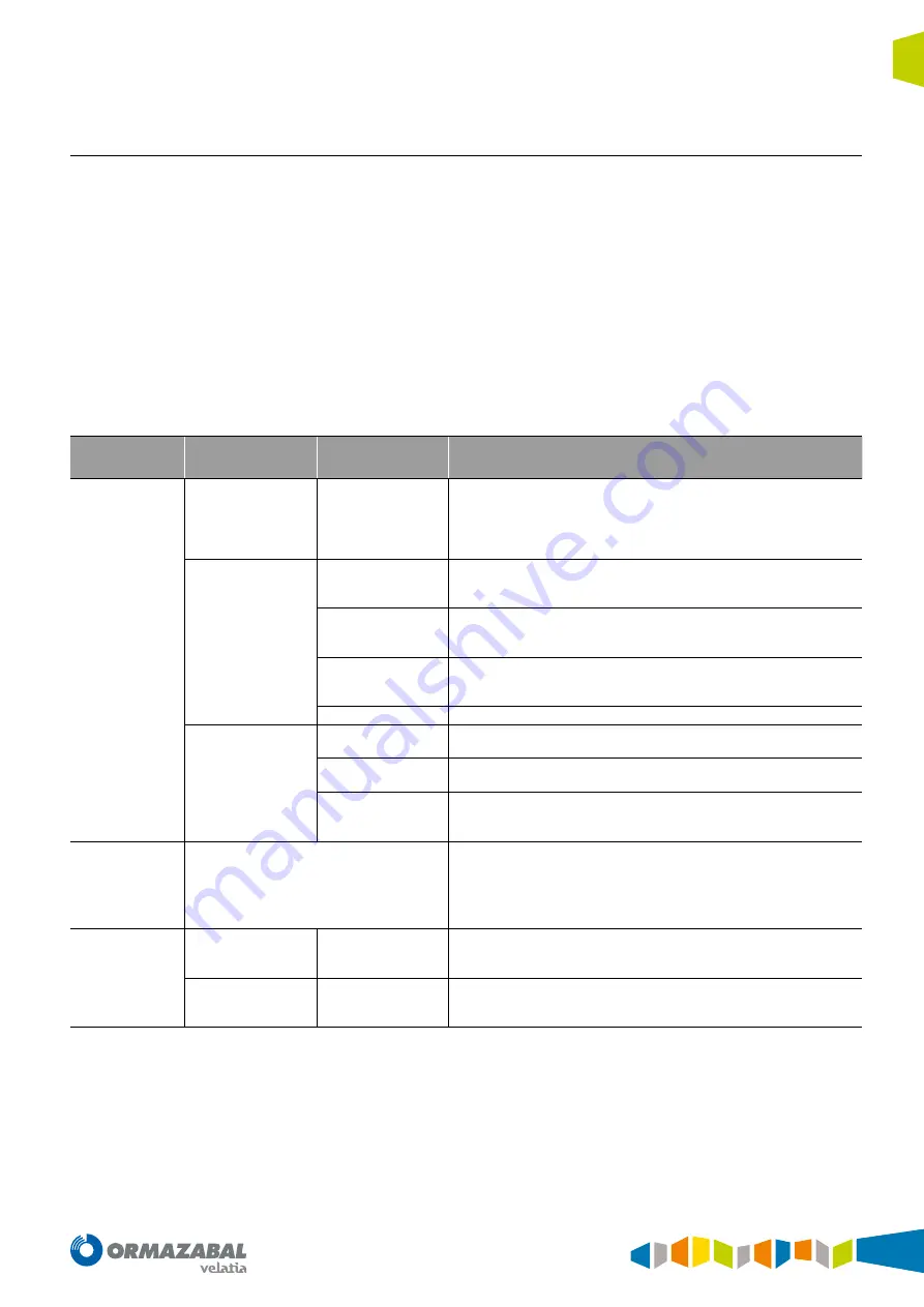
Installation by functional unit can be classified in the
following parts:
Terminals
group
Subgroup
Terminals
Functionality and common use
1.
Interconnection
terminal block
1.1
Power and
communications bus
Interconnection
connectors
• Interconnection between cubicles.
• Interconnection power system and communications bus.
• Cubicle power supply (relay, coils, motors, etc.)
• Relay communication.
• Cabled signalling exchange.
1.2
Relay terminal block
Terminal block–A
• Interconnection terminal block between the cubicle terminal block and
the relay.
• Accessible points for checks or tests.
Terminal block–G
• Voltage and current secondary circuit shortable and disconnectable
terminals.
• Current and voltage injection for relay tests through the secondary circuit.
Temperature bus
connector
• Communications interconnection connector between relay and
temperature sensors and power supply sensors.
• Connection point for new sensors and sensor check.
P.M.
• Additional energy module for bistable release.
1.3.
Cubicle terminal block
Terminal block-52
• Interconnection terminal block between the relay terminal block and
the switch control.
Terminal block–J
• Interconnection terminal block between earthing and busbar sectionaliser
control with the relay terminal block.
Connector-CTD
• Connector which interconnects with the relay (optionally with the energy
module) and the Binox bistable.
• Checkpoint relay trip and Binox bistable activation correct.
2.
ekor
.rpa-110-v
or
ekor
.rpa-120-v
electronic relay
* See relay terminals.
* See relay terminals functionality.
3.
Voltage and
current sensors
3.1.
Current transformer
connectors
Connector-Ip
• Interconnection connector between current sensors and test terminal block.
• Sensor disconnection in cable compartment.
3.2.
Capacitive sensor
connectors
Connector-D
• Interconnection connector between voltage sensors and test terminal block.
• Sensor disconnection in cable compartment.
Table 8.4.
Installation
Summary of Contents for ekor.rpa Series
Page 115: ......


