IG-267-EN versión 01; 07/04/2017
18
Metering functions
General Instructions
ekor
.rpa
3. Metering functions
3.1. Current and voltage metering
The unit has four current reading inputs (I
A
, I
B
, I
C
and I
NS
)
and three voltage reading inputs (V
A
, V
B
and V
C
). Each of
them are conditioned and digitised in order to carry out the
calculation.
The design of the equipment and sensors, along with their
integration in the cubicle, form an assembly which works
as a single unit to achieve maximum immunity and quality
of the signal to be measured, both in the 50 Hz and 60 Hz
networks.
The signal transduction and conditioning stages are
designed to ensure the sensor and relay assembly
reproduces both the magnitude and the phase of the
current and voltage signals of the distribution network.
This ensures optimal performance in real-time applications,
with protection algorithms, in all operation conditions and
in supply quality or load monitoring meterings.
The samples obtained for I
N
and V
N
, calculated by the sum
of samples of the corresponding phase signals, must be
added to the voltage and current inputs sampled directly.
These calculated signal characteristics are equivalent to
those obtained by vector sum of the conventional sensor
signals.
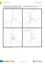
The meterings for supervision of current and voltage are
measured integrated for 1.28 seconds and represented in
phasorial mode ( argument). Network load status
is therefore updated regularly.
The current and voltage meterings are:
• Line currents I
A
, I
B
and I
C
.
• Line voltage: U
AB
, U
BC
and U
CA
and Line voltages: V
A
, V
B
and V
C
.
• Residual currents and voltages. Represented as: I
N
/I
NS
(3I
o
) and V
N
(3V
o
).
Figure 3.1.
Current and voltage metering
The final calibration is the overall calibration of sensors,
metering equipment, cabling and switchgear, and is
validated in an exhaustive test plan carried out in a
controlled environment which reproduces the reality of the
medium-voltage electrical distribution network.
All this process includes different scenarios:
• Maximum electromagnetic interference and temperature
rise scenarios of the assembly, carried out at rated
switchgear current.
• Maximum thermal variation scenarios, carried out in a
climate chamber between -10 °C and 60 °C.
• Scenarios with highly aggressive transient disturbance,
power and lightning impulse tests with medium-voltage
levels.
• etc.
These tests conclude in points such as: the ratio of the
number of turns of the current transformers, impedance
of the voltage reading inputs, etc. All this is tested and
validated on the final solution delivered to the customer.
Summary of Contents for ekor.rpa Series
Page 115: ......


