4848
GENERAL INSTRUCTIONS FOR PF
MODULAR ENCLOSURES FOR
TRANSFORMER SUBSTATIONS
IG-021-GB
version 07
29.08.2008
Page 9 of 48
Confirm that the crane is sufficiently powerful to unload the components comprising the
transformer substation (the maximum weight of any individual part is about 2500 kg) and that
it can move them the distances required to install the transformer substation.
3.3. PREPARING THE GROUND
3.3.1. Excavation Dimensions
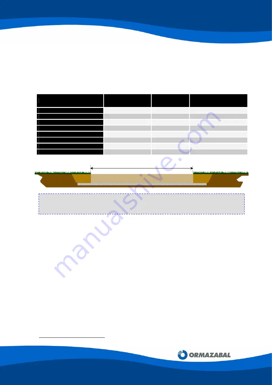
The excavation dimensions depend on the enclosure model:
MODEL
LENGTH (L) [mm]
WIDTH [mm]
DEPTH [mm]
PF201 / PF301
3420
3420
650
PF202 / PF302
5680
3420
650
PF203 / PF303
8040
3420
650
PF204 / PF304
10400
3420
650
PF205 / PF305
12760
3420
650
PF2015 / PF3015
4500
3420
650
PF2030 / PF3030
8040
3420
650
PF3035
9220
3420
650
3.3.2. Types of Ground
The type of ground on which the PF Modular Transformer Substation will rest is an essential
factor, given the weight of the equipment. The ground could subside or become uneven, or
could provide differential settlements, causing cracks in the enclosure.
There are two types of ground:
A) Hard Grounds
:
Grounds where the soil is settled and properly compacted by natural
causes, with a strength of at least 1 kg/cm
2
.
When the excavation is finished, a sand layer of approximately 100 mm should be laid
down and compacted until a person can walk on it without leaving footprints (only a
surface mark).
Once the levelling boards
[4]
have been removed, the gaps they leave should be filled with
sand. Take the measures appropriate to each case to prevent the filling sand from
eroding.
[4]
See section 3.4.
Levelling process
L
NOTE:
For other configurations, the distance L must be increased by 2360 mm for each
additional 200/300 series panel, and by 3540 mm for each additional 2015/3015 series
panel. Consult Ormazabal’s Technical - Commercial Department.


