background image

In view of the constant evolution in standards and design, the characteristics of the elements contained in this manual are subject 

to change without prior notice. These characteristics, as well as the availability of components, are subject to confirmation by 

Ormazabal

.

CAUTION! 

When medium-voltage equipment is operating, certain components are live, other parts may be in movement and some may 

reach high temperatures. Therefore, the use of this equipment poses electrical, mechanical and thermal risks.
In order to ensure an acceptable level of protection for people and property, and in compliance with applicable environmental 

recommendations, 

Ormazabal

 designs and manufactures its products according to the principle of integrated safety, based on 

the following criteria:

 • Elimination of hazards wherever possible.
 • Where elimination of hazards is neither technically nor economically feasible, appropriate protection functions are 

incorporated in the equipment.

 • Communication about remaining risks to facilitate the design of operating procedures which prevent such risks, 

training for the personnel in charge of the equipment, and the use of suitable personal protective equipment.

 • Use of recyclable materials and establishment of procedures for the disposal of equipment and components so 

that once the end of their service lives is reached, they are duly processed in accordance, as far as possible, with the 

environmental restrictions established by the competent authorities.

Consequently, the equipment to which the present manual refers complies with the requirements of section 11.2 of Standard 

IEC 62271-1. It must therefore only be operated by appropriately qualified and supervised personnel, in accordance with the 

requirements of standard EN 50110-1 on the safety of electrical installations and standard EN 50110-2 on activities in or near 

electrical installations. Personnel must be fully familiar with the instructions and warnings contained in this manual and in other 

recommendations of a more general nature which are applicable to the situation according to current legislation

[1]

.

The above must be carefully observed, as the correct and safe operation of this equipment depends not only on its design but also 

on general circumstances which are in general beyond the control and responsibility of the manufacturer. More specifically:

 • The equipment must be handled and transported appropriately from the factory to the place of installation.
 • All intermediate storage should occur in conditions which do not alter or damage the characteristics of the equipment 

or its essential components.

 • Service conditions must be compatible with the equipment rating.
 • The equipment must be operated strictly in accordance with the instructions given in the manual, and the applicable 

operating and safety principles must be clearly understood.

 • Maintenance should be performed properly, taking into account the actual service and environmental conditions in 

the place of installation.

The manufacturer declines all liability for any significant indirect damages resulting from violation of the guarantee, under any 

jurisdiction, including loss of income, stoppages and costs resulting from repair or replacement of parts.

Warranty

The manufacturer guarantees this product against any defect in materials and operation during the contractual period. In the 

event that defects are detected, the manufacturer may opt either to repair or replace the equipment. Improper handling of this 

equipment and its repair by the user shall constitute a violation of the guarantee.

Registered Trademarks and Copyrights

All registered trademarks cited in this document are the property of their respective owners. The intellectual property of this manual 

belongs to 

Ormazabal

.

[1] 

For example, in Spain the “Regulation on technical conditions and guarantees for safety in high-voltage electrical installations” – Royal Decree 

337/2014 is obligatory.

Summary of Contents for pfu48/27

Page 1: ...LIB pfu for large sized applications Prefabricated ground level enclosure General instructions IG 262 EN versi n 02 26 04 2018...

Page 2: ...ectrical installations Personnel must be fully familiar with the instructions and warnings contained in this manual and in other recommendations of a more general nature which are applicable to the si...

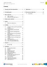
Page 3: ...es with monoblock body and tank 14 6 2 1 Handling of enclosures with four DEHA anchors 14 6 2 2 Handling of enclosures with eight DEHA anchors 16 6 3 Handling the roof 17 6 3 1 Covers with four thread...

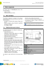
Page 4: ...panels connected by mechanical joints to make up a self supporting enclosure with sufficient structural capacity to withstand the stresses they are subjected to throughout their working life includin...

Page 5: ...ications Standards applied 2 Standards applied The pfu meets the design requirements set out in Standard IEC 62271 202 high voltage low voltage prefabricated transformer substations and applicable reg...

Page 6: ...e prefabricated enclosure is made up of amongst others the following elements Prefabricated concrete tank Prefabricated concrete body Formed by reinforced concrete panels mechanically attached Prefabr...

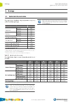
Page 7: ...accordance with Standard IEC 62271 1 In the enclosure it is understood that normal indoor service conditions in accordance with Standard IEC 62271 1 prevail Installation Outdoor Solar radiation 1000...

Page 8: ...ease check with Ormazabal Weight of the empty enclosure without switchgear Table 5 1 pfu dimensions variation ranges The table below shows a series of possible variants as an example pfu 48 27 pfu 60...

Page 9: ...ific section with the corresponding instructions Instructions for enclosures with separate body and tank in section 6 1 Instructions for enclosures with monoblock body and tank in section 6 2 Instruct...

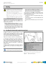
Page 10: ...chains Hook the top slings on the crane hook 1 Top slings 2 Lifting beam 2 1 Larger lifting beam shackle 2 2 Smaller lifting beam shackle 3 Bottom slings or chains 4 Universal head hooks DEHA KA type...

Page 11: ...over can be handled together Proceed as follows 1 Make sure the tools and equipment shown in Figure 6 7 are available ensuring the larger shackle of the lifting beam is joined to the top slings The sm...

Page 12: ...tions in section 8 5 Assembly process for enclosures with separate body and tank 4 Once the pfu body is in place uncouple the universal head hooks from the body s DEHA anchors 6 1 3 Handling of bodies...

Page 13: ...r chains 4 Universal head hooks DEHA KA type Slings or chains in accordance with the detailed study of the handling process The tank and body may require different universal head hooks Figure 6 11 Fas...

Page 14: ...ment are required in order to handle enclosures with monoblock body and tank The amounts of each tool or equipment required will vary in accordance with the detailed handling study 1 Top slings 2 Lift...

Page 15: ...ft type or adjustable length 2 1 Larger lifting beam shackle 2 2 Smaller lifting beam shackle 3 Bottom slings or chains 4 Universal head hooks DEHA KA type Slings or chains in accordance with the deta...

Page 16: ...the lifting beams is attached to the top slings facing upwards The smaller shackle is facing downward attached to the slings or chains Hook the top slings on the crane hook 1 Top slings 2 Lifting beam...

Page 17: ...e M20 threaded eyebolts 3 Flat head screwdriver Figure 6 23 Equipment and tools required Proceed as follows to handle the cover 1 Remove the four plugs which cover the threaded inserts of the cover us...

Page 18: ...ts in the inserts throughout their length 3 Make sure the tools shown in Figure 6 26 are available ensuring the larger shackle of the lifting beam is joined to the top slings The smaller shackle is at...

Page 19: ...vehicles The Generic Authorisation for Special Transport when required must be obtained in advance taking into account the legislation in the countries of transit during transport Whenever the enclosu...

Page 20: ...mage or absences are observed immediately inform the transport agent and Ormazabal 8 2 Location The site location should be precisely defined indicating the levels of alignment and height of the possi...

Page 21: ...ordance with the General Safety Plan There must be a person designated as the Prevention Resource throughout the duration of the activity on site The minimum health and safety requirements for constru...

Page 22: ...are prepared with specific procedures All other ground is prepared following the procedure set out for ground in normal conditions Normal conditions The reference level boards are positioned in accor...

Page 23: ...gure 8 5 Sloping ground Ground with a high water table Proceed as follows when the water table level is high 1 Establish the water table level 2 Only excavate the required depth levelling as indicated...

Page 24: ...ection 6 1 1 Handling the tank 2 Check the tank level with the spirit level 3 Position the EPDM adhesive band on the top face of the tank covering the whole perimeter Remove the protection from the fr...

Page 25: ...uit The operational earthing circuit neutral joins the transformer s neutral to the operational earthing switch box The exterior operational earthing circuit connects to this switch box Figure 8 12 Ex...

Page 26: ...al instructions pfu for large sized applications 9 Maintenance The pfu does not require specific maintenance It may occasionally require the lubricating of locks and the checking of the ventilation gr...

Page 27: ...ally of materials which at the end of their life cycle are catalogued as Inert Industrial Waste In accordance with Ormazabal s commitment to the Environment endorsed by the ISO 14001 certificate for i...

Page 28: ...Subject to change without prior notice For further information contact Ormazabal Ormazabal ZAMUDIO Spain www ormazabal com...

Reviews: