IG-284-EN version 03; 06/05/2020
25
General Instructions
cgm
.800: Medium-voltage switchgear with integrated insulation in SF
6
gas
up to 36 kV in accordance with IEC Standard with rated current up to 800 A
Installation
4.5.2. Fastening to the floor by anchoring
[9]
See section “5. Recommended sequence of operations”.
If the fl oor of the facility is level enough, it is advisable to
install the medium-voltage cubicle anchored directly to the
fl oor.
The sequence for anchoring the cubicles to the fl oor is as
follows:
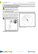
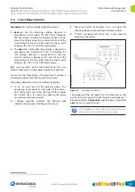
1.
The cubicle's switch must be in the earthing position.
[9]
By default, the cubicles are supplied with the switch in
earthing position. Except in circuit breaker functions,
which will be in isolating position.
2.
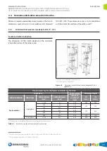
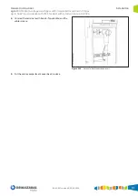
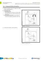
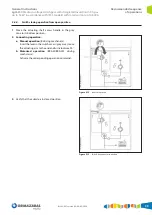
Remove the cable compartment cover, using the central
handle on the cover to pull it up and forward.
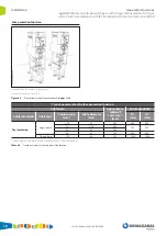
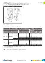
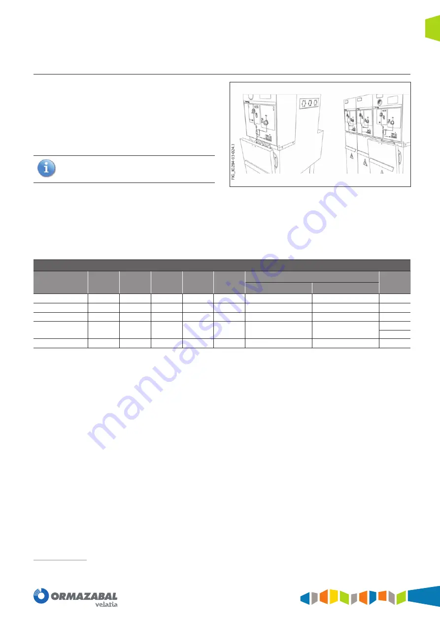
Figure 4.12.
Removing the cable compartment cover
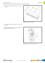
3.
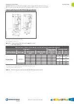
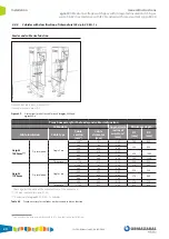
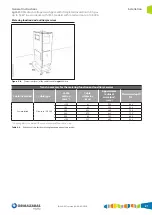
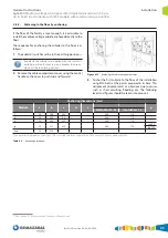
Anchor the fi rst cubicle to the fl oor of the installation
using M10 bolts at the points prepared in its base. This
will prevent displacements or vibrations due to causes
such as short-circuiting, fl ooding, etc. The following
levels and fi gures should be taken into account:
Anchoring dimensions [mm]
Module
a
b
c
d
e
f
g
Internal arc 0.5 s
Internal arc 1 s
l
50
368
245
-
-
540
710
-
p
50
430
60
-
-
540
710
-
v
50
550
325
-
-
540
710
-
rc
50
317
435
-
-
540
710
-rci 209
-rcd 158
ma
36
525
-
-
-
-
-
-
(*) Separation between anchors for 1100 mm wide cubicles; separation of 830 mm for 900 mm wide cubicles.
Table 4.9.
Anchoring dimensions
Summary of Contents for velatia cgm.800
Page 71: ......

