IG-284-EN version 03; 06/05/2020
29
General Instructions
cgm
.800: Medium-voltage switchgear with integrated insulation in SF
6
gas
up to 36 kV in accordance with IEC Standard with rated current up to 800 A
Installation
4.8. Cable connections
[10]
[11]
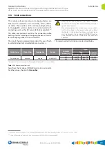
The medium-voltage incoming and outgoing feeders are
linked to the transformer or, occasionally, other cubicles
via cables. These cables and the corresponding bushings
in the
cgm
.800 system cubicles can be connected with
connecting points, either IEC type or IEEE-386 compliant.
[10]
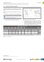
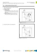
The cable compartment contains the connecting cable
bushings for the incoming and outgoing feeders, as well as
for the outgoing feeders to the transformer.
The size of the cable compartment allows the use of both
insulated and partially insulated cable connectors.
[11]
Never touch live connectors, not even screened
connectors. Screening does not constitute a protection
against direct contact.
When the equipment is in service and a reserve cubicle
is left with voltage in the upper busbar and without
the cables in the bottom bushings, insulating plugs
must be placed in the bushings (EUROMOLD type) or
close the earthing switch and lock that position with
a padlock.
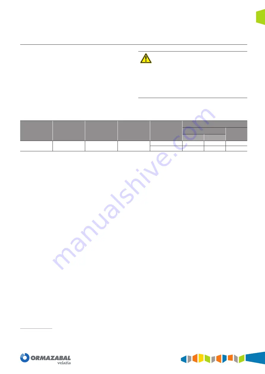
The recommended terminations are described below:
Cable type
Protection
Connector
Events
Current
Rated [A]
Type
Type
Section
[mm
2
]
24 kV
36 kV
Dry insulation
Screened
Angled
EUROMOLD*
800
K440TB
M440TB
185-630
800
K484TB
M484TB
35-630
* Connectors recommended for
Ormazabal
’s
cgm
.800 system cubicles.
Table 4.10.
Recommended terminals
Apart from the list above, CENELEC terminals are also valid.
For other values, check with
Ormazabal
.
In accordance with figure 11 13 of Standard IEEE 386: “600 A deadbreak interface nº1 15.2 kV or nº1 21.1 kV”.
Using fully insulated connectors in accordance with HD 629 is recommended.
Summary of Contents for velatia cgm.800
Page 71: ......


