IG-247-EN version 02; 08/12/2020
6
Description and main characteristics
General instructions
cms
.21
The doors have grilles in the top and bottom sections for
ventilation of
cms
.21.
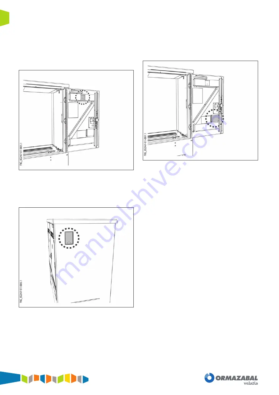
There is an insulating plate on the inside of the door, in the
top section, in order to fasten a communications antenna
when necessary.
Figure 1.3.
Communications antenna mount
The top right side has pre-marking to install an exterior
antenna under insulating enclosure. A blanked hole
allows the transit of the antenna cable to the inside of the
enclosure.
Figure 1.4.
Pre-marking for exterior antenna mount.
The document holder is located on the inside of the right
door, with these General Instructions for
cms
.21 (
IG-247
)
and the General Instructions of the medium voltage
switchgear installed.
Figure 1.5.
Document holder
The bottom of the enclosure has a trench with blanked
holes for medium voltage cable transit.
A removable concrete cover closes the top of the enclosure
and allows the switchgear to be replaced.


