


IG-175-EN version 02; 17/06/2016
19
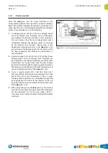
General Instructions
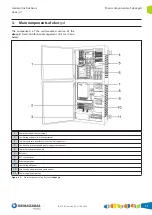
ekor.gid
Main components of ekor.gid
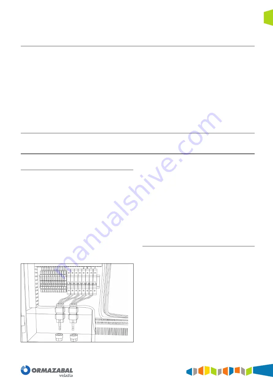
3.4.7. Connection and Protection Components
The ekor.gid Smart Distribution Management Unit includes
miniature circuit-breakers for protecting the different
electrical components installed inside it. This ensures the
integrity of the system against overvoltage problems
and prevents unnecessary maintenance operations to
replace defective components or components that are not
operating properly as a consequence of these overvoltages.
The available protection components are one independent
four-pole miniature circuit-breaker (3 phases and neutral)
for each one of the Low Voltage boards that are monitored
via the ekor.gid unit.
The characteristics of the four-pole miniature circuit-
breakers are the following:
4. I
n
= 1 A
1. I
cu
= 25 kA
2. I
ca
= 75% I
cu
3. D type curve
As connection components, the ekor.gid unit includes
short-circuitable and disconnectable terminals with 6
currents per each Low Voltage board to be monitored.
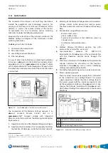
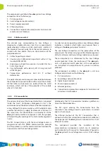
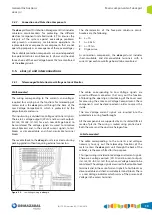
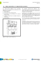
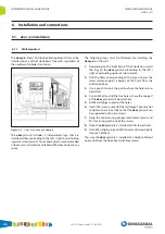
3.5. ekor.gid unit interconnections
3.5.1. Telemanaged Substation/Low Voltage network Monitor
Wall-mounted
The wiring corresponding to the currents and voltages
required for carrying out the functions for telereading of
meters enters the ekor.gid unit through the base of the
Low Voltage Compartment, which is protected by the
polycarbonate enclosure.
This input wiring is divided into Voltage and Current signals.
There are 4 voltage outputs (3P+N) and 6 current outputs
(Ia1-Ia2, Ib1-Ib2, Ic1-Ic2) for each Low Voltage board to
be monitored. The voltage signals are wired to miniature
circuit-breakers and, in the case of current signals, to test
blocks or disconnectable and short-circuitable terminal
blocks.
These cable feeds to the ekor.gid unit are carried out using
packing glands without requiring external connectors.
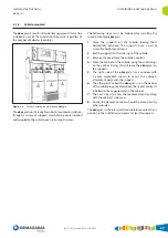
Figure 3.2.
Low Voltage wiring in
ekor.gid
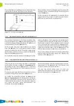
The cables corresponding to Low Voltage signals are
wired to different connectors that carry out the function
of blocking the opening or interlocking of the cover used
for accessing the entire Low Voltage Compartment. These
components must be disconnected in order to access the
inside.
The Low Voltage current signals are inserted into the
protected area using feedthroughs.
All the components are supported by an insulated DIN rail
made of plastic. The wiring is routed using plastic ducts.
Both the wires and the ducts are halogen free.
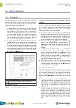
Cubicle-mounted
The cable corresponding to the currents and voltages
necessary to carry out the telereading functions of the
meters enters the ekor.gid-s unit through the back of the
cabinet, via the access fitted for this purpose.
This input wiring is divided into Voltage and Current signals.
There are 4 voltage outputs (3P+N) and 6 current outputs
(Ia1-Ia2, Ib1-Ib2, Ic1-Ic2) for each Low Voltage board to be
monitored. The voltage signals are wired to the double-level
terminals and, in the case of current signals, to test blocks or
disconnectable and short-circuitable terminal blocks. There
is a Low Voltage indicator which warns of the presence of
Voltage in the access terminals.
Summary of Contents for velatia ekor.gid
Page 31: ......


