


IG-175-EN version 02; 17/06/2016
23
General Instructions
ekor.gid
ekor.gid models
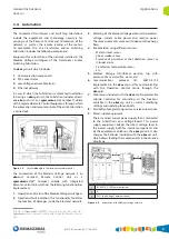
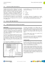
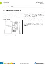
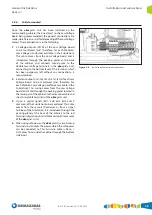
4.2. Standard interior wall-mounted ekor.gid
The Standard Interior ekor.gid Wall-Mounted Smart
Distribution Management Unit includes the following main
functions:
1. Telemanagement
2. Monitoring of the Low Voltage network
3. Interconnection with Monitoring of the Medium
Voltage network
4. Communications
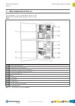
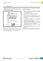
Figure 4.2.
Standard interior
ekor.gid
The Standard Interior ekor.gid Smart Distribution
Management Unit includes a power supply unit and is
installed in Substations used for Remote Meter readings
or even Substations that are to be monitored (in these
cases, power for the component that monitors the Medium
Voltage is provided by the ekor.gid).
Additionally, the Standard Interior ekor.gid unit can carry
out the Advanced Monitoring of the Low Voltage network
when it is associated with Low Voltage sensors, which are
in charge of carrying out the meterings required in the Low
Voltage Board in order to implement these functions.
In the event that the Low Voltage Board does not include
sensors, the Basic Monitoring of Low Voltage is carried out.
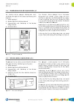
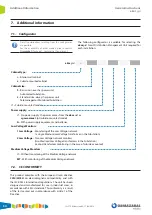
4.3. Interior cubicle-mounted ekor.gid-s
The ekor.gid-s interior cubicle-mounted Smart Distribution
Management Unit has the following main functions:
1. Telemanagement
2. Monitoring of the Low Voltage network
3. Interconnection with Monitoring of the Medium
Voltage network
4. Collection of signals from the Substation (Flood, Fire,
Intruder, etc.).
5. Communications
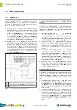
Figure 4.3.
Cubicle-mounted
ekor.gid-s
The ekor.gid-s cubicle-mounted Smart Distribution
Management Unit does not have a power unit, but can be
operated simply using the safe power of the charger with
batteries, benefiting from its layout close to the cubicle-
mounted automation.
Additionally, this Basic ekor.gid unit can carry out the
Advanced Monitoring of the Low Voltage network when it
is associated with Low Voltage sensors in charge of carrying
out the meterings required in the Low Voltage Board in
order to implement these functions.
In the event that the Low Voltage Board does not include
sensors, the Basic Monitoring of the low Voltage network is
carried out.
The ekor.gid-s can be used to collect activation signals from
the sensors of the Substation. It is configured to transmit
the signal from the limit switch to be installed in a door in
order to detect intruders, or the buoy or smoke detector.
Summary of Contents for velatia ekor.gid
Page 31: ......


